

Question: Write a single VHDL file (led_control.vhd) with the functional description of the proposed led control system. For this lab it is requested to design a
Write a single VHDL file (led_control.vhd) with the functional description of the proposed led control system.
For this lab it is requested to design a finite state machine to control the operation of a LED-light system for bicycles. The system is provided of the following:
1-A LED-light, controlled by a signal called light.
2-A pushbutton, which controls a signal named puls, which is active at high level.
3-A clock input signal, clk. It will have a frequency of 8 Hz (period 125 ms)
4-A reset signal, rst, synchronous and active low
Figure 1 shows the behavior of the system. With each press of the push button the LED light cycles through three modes of operation, called modes A, B and C. These modes are described in the table below. The system will switch from mode C to mode A when the push-button is next pressed.
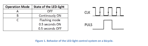
Each time the pushbutton is pressed, a pulse is generated on the signal puls, of duration 1 clock cycle and centered around a rising edge of the clock signal, as shown in Figure 1.
Figure 2 shows the state diagram for a Moore finite state machine that allows the behavior described. In this case the clock frequency used was 4 Hz. Students with a clk signal of frequency 6 Hz should add two additional states, and those with frequency 8 Hz should add four additional states. In any case, when switching from operating mode B to C, the LED light should always start the ON cycle for 0.5 seconds (switching from state B to C1 in Figure 2).
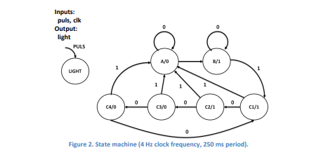
Therefore, this state machine will have to be implemented with slight modifications depending on the clock frequency, 6 Hz or 8 Hz. In addition, you will have to take into account the reset signal, rst, which is synchronous and always returns the system to state A (this signal is not shown in the diagram in Figure 2).
Write a single VHDL file (led_control.vhd) with the functional description of the proposed led control system. It should be implemented with a Moore finite state machine and must have the following entity declaration:
entity led_control is Port ( clk : in STD_LOGIC; rst : in STD_LOGIC; puls : in STD_LOGIC; light : out STD_LOGIC); end led_control;
Operation Mode A B C CLK inn State of the LED-light OFF Continously ON Flashing mode 0.5 seconds ON 0.5 seconds OFF PULS Figure 1. Behavior of the LED light control system on a bicycle. Inputs: puls, clk Output: light PULS A/0 A/ B/1 LIGHT 04/0 C3/0 02/1 01/1 0 Figure 2. State machine (4 Hz clock frequency, 250 ms period). 4
Step by Step Solution
There are 3 Steps involved in it

Get step-by-step solutions from verified subject matter experts