

Question: WRITE IN MATLAB SCRIPT *-ww In this you will explore the dynamics of a simple RC circuit. Consider a RC circuit as shown in figure.
WRITE IN MATLAB SCRIPT
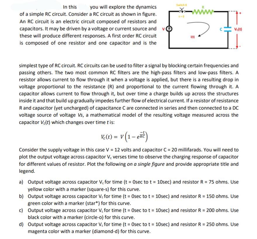
*-ww In this you will explore the dynamics of a simple RC circuit. Consider a RC circuit as shown in figure. An RC circuit is an electric circuit composed of resistors and capacitors. It may be driven by a voltage or current source and v these will produce different responses. A first order RC circuit is composed of one resistor and one capacitor and is the Ve(t) ift) simplest type of RC circuit. RC circuits can be used to filter a signal by blocking certain frequencies and passing others. The two most common RC filters are the high-pass filters and low-pass filters. A resistor allows current to flow through it when a voltage is applied, but there is a resulting drop in voltage proportional to the resistance (R) and proportional to the current flowing through it. A capacitor allows current to flow through it, but over time a charge builds up across the structures inside it and that build up gradually impedes further flow of electrical current. If a resistor of resistance Rand capacitor (yet uncharged) of capacitance C are connected in series and then connected to a DC voltage source of voltage Vs, a mathematical model of the resulting voltage measured across the capacitor Ve(t) which changes over time tis: V.(t) = v(1-ep) Consider the supply voltage in this case V = 12 volts and capacitor C = 20 millifarads. You will need to plot the output voltage across capacitor Ve verses time to observe the charging response of capacitor for different values of resistor. Plot the following on a single figure and provide appropriate title and legend. a) Output voltage across capacitor Ve for time (t = Osec to t = 10sec) and resistor R = 75 ohms. Use yellow color with a marker (square-s) for this curve. b) Output voltage across capacitor Ve for time (t = Osec to t = 10sec) and resistor R = 150 ohms. Use green color with a marker (star*) for this curve. c) Output voltage across capacitor Ve for time (t = Osec to t = 10sec) and resistor R = 200 ohms. Use black color with a marker (circle-o) for this curve. d) Output voltage across capacitor Ve for time (t = Osec to t = 10 sec) and resistor R = 250 ohms. Use magenta color with a marker (diamond-d) for this curve. *-ww In this you will explore the dynamics of a simple RC circuit. Consider a RC circuit as shown in figure. An RC circuit is an electric circuit composed of resistors and capacitors. It may be driven by a voltage or current source and v these will produce different responses. A first order RC circuit is composed of one resistor and one capacitor and is the Ve(t) ift) simplest type of RC circuit. RC circuits can be used to filter a signal by blocking certain frequencies and passing others. The two most common RC filters are the high-pass filters and low-pass filters. A resistor allows current to flow through it when a voltage is applied, but there is a resulting drop in voltage proportional to the resistance (R) and proportional to the current flowing through it. A capacitor allows current to flow through it, but over time a charge builds up across the structures inside it and that build up gradually impedes further flow of electrical current. If a resistor of resistance Rand capacitor (yet uncharged) of capacitance C are connected in series and then connected to a DC voltage source of voltage Vs, a mathematical model of the resulting voltage measured across the capacitor Ve(t) which changes over time tis: V.(t) = v(1-ep) Consider the supply voltage in this case V = 12 volts and capacitor C = 20 millifarads. You will need to plot the output voltage across capacitor Ve verses time to observe the charging response of capacitor for different values of resistor. Plot the following on a single figure and provide appropriate title and legend. a) Output voltage across capacitor Ve for time (t = Osec to t = 10sec) and resistor R = 75 ohms. Use yellow color with a marker (square-s) for this curve. b) Output voltage across capacitor Ve for time (t = Osec to t = 10sec) and resistor R = 150 ohms. Use green color with a marker (star*) for this curve. c) Output voltage across capacitor Ve for time (t = Osec to t = 10sec) and resistor R = 200 ohms. Use black color with a marker (circle-o) for this curve. d) Output voltage across capacitor Ve for time (t = Osec to t = 10 sec) and resistor R = 250 ohms. Use magenta color with a marker (diamond-d) for this curve
Step by Step Solution
There are 3 Steps involved in it

Get step-by-step solutions from verified subject matter experts