

Question: x = 5 , y = 4 z = 2 Problem 2 : You are asked to design the beam in figure 2 - 1
x y z
Problem :
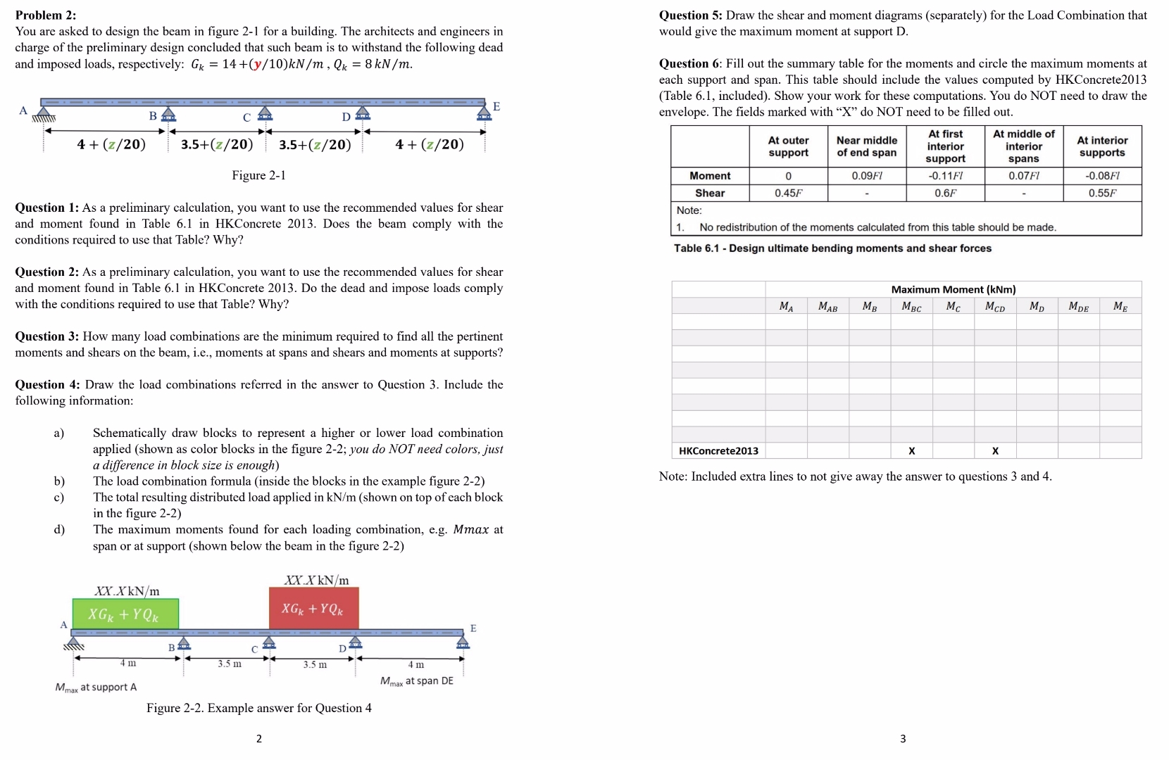
You are asked to design the beam in figure for a building. The architects and engineers in charge of the preliminary design concluded that such beam is to withstand the following dead and imposed loads, respectively:
Question : As a preliminary calculation, you want to use the recommended values for shear and moment found in Table in HKConcrete Does the beam comply with the conditions required to use that Table? Why?
Question : As a preliminary calculation, you want to use the recommended values for shear and moment found in Table in HKConcrete Do the dead and impose loads comply with the conditions required to use that Table? Why?
Question : How many load combinations are the minimum required to find all the pertinent moments and shears on the beam, ie moments at spans and shears and moments at supports?
Question : Draw the load combinations referred in the answer to Question Include the following information:
a Schematically draw blocks to represent a higher or lower load combination applied shown as color blocks in the figure ; you do NOT need colors, just a difference in block size is enough
b The load combination formula inside the blocks in the example figure
c The total resulting distributed load applied in shown on top of each block in the figure
d The maximum moments found for each loading combination, eg Mmax at span or at support shown below the beam in the figure
Question : Draw the shear and moment diagrams separately for the Load Combination that would give the maximum moment at support D
Question : Fill out the summary table for the moments and circle the maximum moments at each support and span. This table should include the values computed by HKConcreteTable included Show your work for these computations. You do NOT need to draw the envelope. The fields marked with do NOT need to be filled out.
tabletableAt outersupporttableNear middleof end spantableAt firstinteriorsupporttableAt middle ofinteriorspanstableAt interiorsupportsMoment
Problem :
You are asked to design the beam in figure for a building. The architects and engineers in charge of the preliminary design concluded that such beam is to withstand the following dead and imposed loads, respectively:
Question : As a preliminary calculation, you want to use the recommended values for shear and moment found in Table in HKConcrete Does the beam comply with the conditions required to use that Table? Why?
Question : As a preliminary calculation, you want to use the recommended values for shear and moment found in Table in HKConcrete Do the dead and impose loads comply with the conditions required to use that Table? Why?
Question : How many load combinations are the minimum required to find all the pertinent moments and shears on the beam, ie moments at spans and shears and moments at supports?
Question : Draw the load combinations referred in the answer to Question Include the following information:
a Schematically draw blocks to represent a higher or lower load combination applied shown as color blocks in the figure ; you do NOT need colors, just a difference in block size is enough
b The load combination formula inside the blocks in the example figure
c The total resulting distributed load applied in shown on top of each block in the figure
d The maximum moments found for each loading combination, eg Mmax at span or at support shown below the beam in the figure
Question : Draw the shear and moment diagrams separately for the Load Combination that would give the maximum moment at support D
Question : Fill out the summary table for the moments and circle the maximum moments at each support and span. This table should include the values computed by HKConcreteTable included Show your work for these computations. You do NOT need to draw the envelope. The fields marked with do NOT need to be filled out.
tabletableAt outersupporttableNear middleof end spantableAt firstinteriorsupporttableAt middle ofinteriorspanstableAt interiorsupportsMoment
Step by Step Solution
There are 3 Steps involved in it
1 Expert Approved Answer
Step: 1 Unlock

Question Has Been Solved by an Expert!
Get step-by-step solutions from verified subject matter experts
Step: 2 Unlock
Step: 3 Unlock