

Question: X = 9 , Y = 0 , Z = 3 . Q 1 : Draw the internal force diagrams ( N , V ,
X Y Z
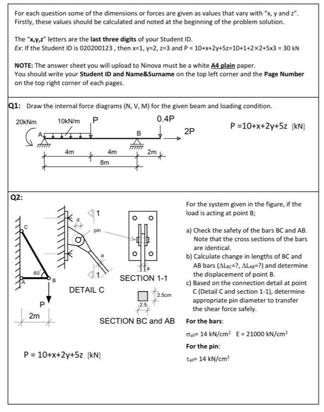
Q: Draw the internal force diagrams for the given beam and loading condition.
For the system given in the figure, if the load is acting at point ;
a Check the safety of the bars and Note that the cross sections of the bars are identical.
b Calculate change in lengths of and bars and determine the displacement of point
c Based on the connection detail at point Detail and section determine appropriate pin diameter to transfer the shear force safely.
For the bars:
For the pin:
Step by Step Solution
There are 3 Steps involved in it
1 Expert Approved Answer
Step: 1 Unlock

Question Has Been Solved by an Expert!
Get step-by-step solutions from verified subject matter experts
Step: 2 Unlock
Step: 3 Unlock