

Question: YAB 4 2 4 3 YAB 4 2 4 3 2 . A schematic system to demonstrate a complete - mixed activated sludge process is
YAB
YAB
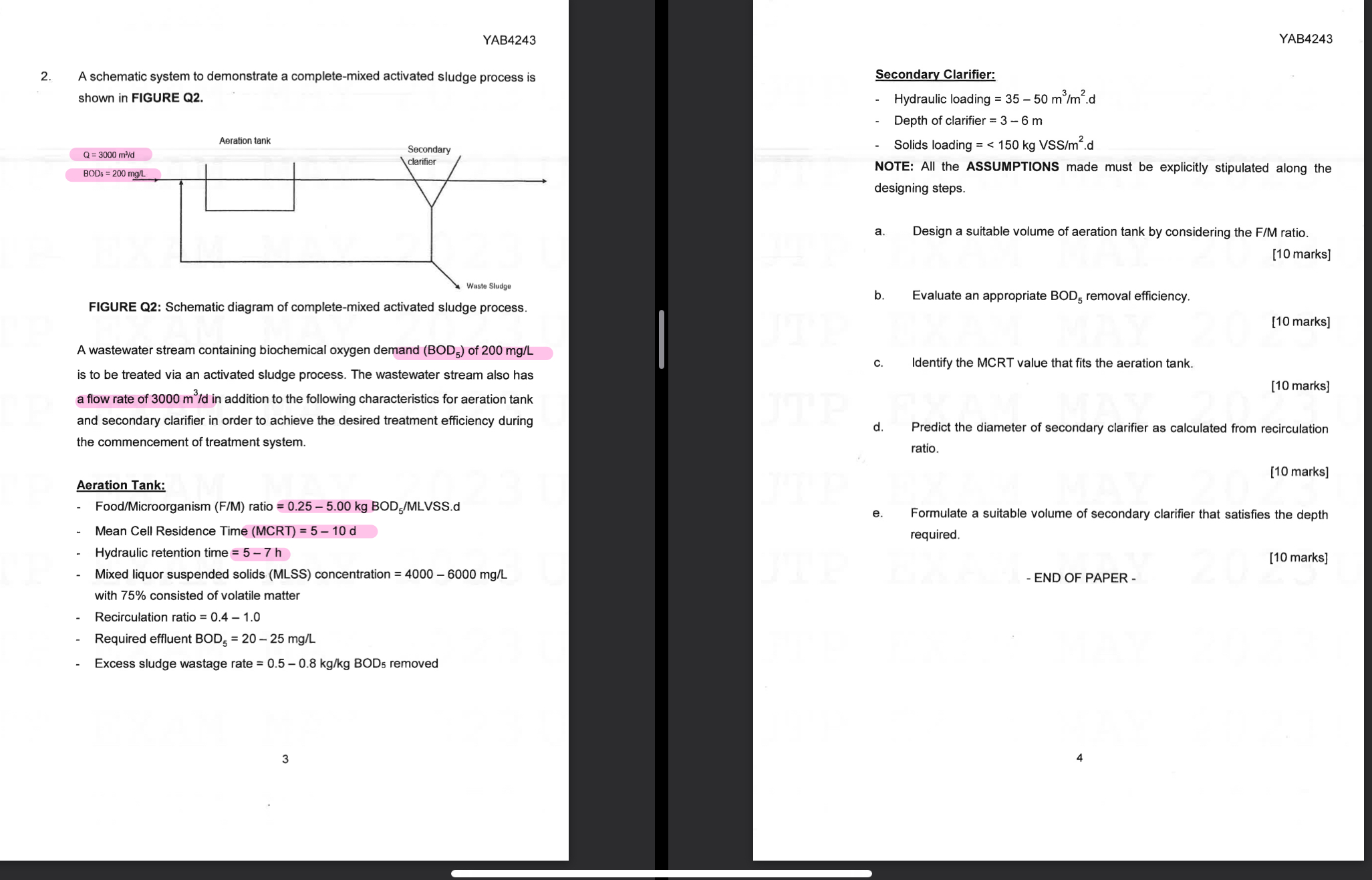
A schematic system to demonstrate a completemixed activated sludge process is shown in FIGURE Q
FIGURE Q: Schematic diagram of completemixed activated sludge process.
A wastewater stream containing biochemical oxygen demand of is to be treated via an activated sludge process. The wastewater stream also has a flow rate of in addition to the following characteristics for aeration tank and secondary clarifier in order to achieve the desired treatment efficiency during the commencement of treatment system.
Aeration Tank:
FoodMicroorganism FM ratio kgBO MLVSSd
Mean Cell Residence Time MCRT
Hydraulic retention time
Mixed liquor suspended solids MLSS concentration with consisted of volatile matter
Recirculation ratio
Required effluent
Excess sludge wastage rate removed
Secondary Clarifier:
Hydraulic loading
Depth of clarifier
Solids loading VSSm
NOTE: All the ASSUMPTIONS made must be explicitly stipulated along the designing steps.
a Design a suitable volume of aeration tank by considering the FM ratio.
marks
b Evaluate an appropriate removal efficiency.
marks
c Identify the MCRT value that fits the aeration tank.
marks
d Predict the diameter of secondary clarifier as calculated from recirculation ratio.
marks
e Formulate a suitable volume of secondary clarifier that satisfies the depth required.
marks
END OF PAPER
Step by Step Solution
There are 3 Steps involved in it
1 Expert Approved Answer
Step: 1 Unlock

Question Has Been Solved by an Expert!
Get step-by-step solutions from verified subject matter experts
Step: 2 Unlock
Step: 3 Unlock