

Question: You are required to design a logic circuit for the state diagram shown in Figure 2 using J-K flip- flops. i) Write down the
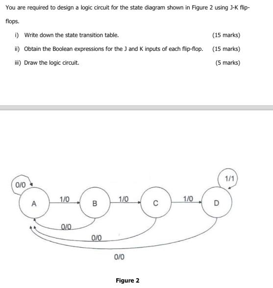
You are required to design a logic circuit for the state diagram shown in Figure 2 using J-K flip- flops. i) Write down the state transition table. (15 marks) ii) Obtain the Boolean expressions for the J and K inputs of each flip-flop. (15 marks) iii) Draw the logic circuit. (5 marks) 0/0 A 1/0 0/0 B 0/0 1/0 0/0 Figure 2 1/0 1/1
Step by Step Solution
There are 3 Steps involved in it
1 Expert Approved Answer
Step: 1 Unlock

Question Has Been Solved by an Expert!
Get step-by-step solutions from verified subject matter experts
Step: 2 Unlock
Step: 3 Unlock