

Question: As an alternative to a lead compensator, lag compensation may be used to provide similar stability margins and steady state errors, albeit with different
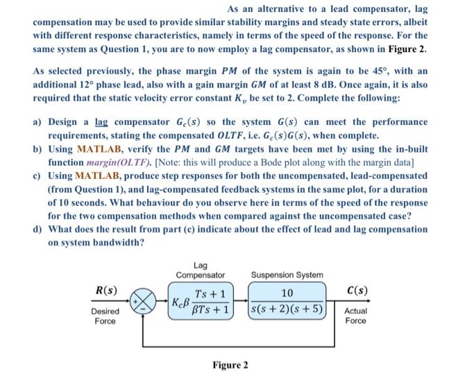
As an alternative to a lead compensator, lag compensation may be used to provide similar stability margins and steady state errors, albeit with different response characteristics, namely in terms of the speed of the response. For the same system as Question 1, you are to now employ a lag compensator, as shown in Figure 2. As selected previously, the phase margin PM of the system is again to be 45, with an additional 12 phase lead, also with a gain margin GM of at least 8 dB. Once again, it is also required that the static velocity error constant K, be set to 2. Complete the following: a) Design a lag compensator Ge(s) so the system G(s) can meet the performance requirements, stating the compensated OLTF, i.e. Ge(s)G(s), when complete. b) Using MATLAB, verify the PM and GM targets have been met by using the in-built function margin(OLTF). [Note: this will produce a Bode plot along with the margin data] c) Using MATLAB, produce step responses for both the uncompensated, lead-compensated (from Question 1), and lag-compensated feedback systems in the same plot, for a duration of 10 seconds. What behaviour do you observe here in terms of the speed of the response for the two compensation methods when compared against the uncompensated case? d) What does the result from part (c) indicate about the effect of lead and lag compensation on system bandwidth? R(s) Desired Force Lag Compensator Ke Ts + 1 BTS + 1 Figure 2 Suspension System 10 s(s+ 2)(s + 5) C(s) Actual Force
Step by Step Solution
3.43 Rating (143 Votes )
There are 3 Steps involved in it
To design a lag compensator and achieve the desired phase margin PM phase lead gain margin GM and static velocity error constant Kv you can follow these steps a Design a Lag Compensator Gs Given that ... View full answer

Get step-by-step solutions from verified subject matter experts