

Question: Your team has been assigned the task of developing a timing logic diagram using the RS5000 PLC program to simulate the mechanical timer of a
Your team has been assigned the task of developing a timing logic diagram using the RS5000 PLC program to simulate the mechanical timer of a washing machine product. Design specifics and program sequence are as follows
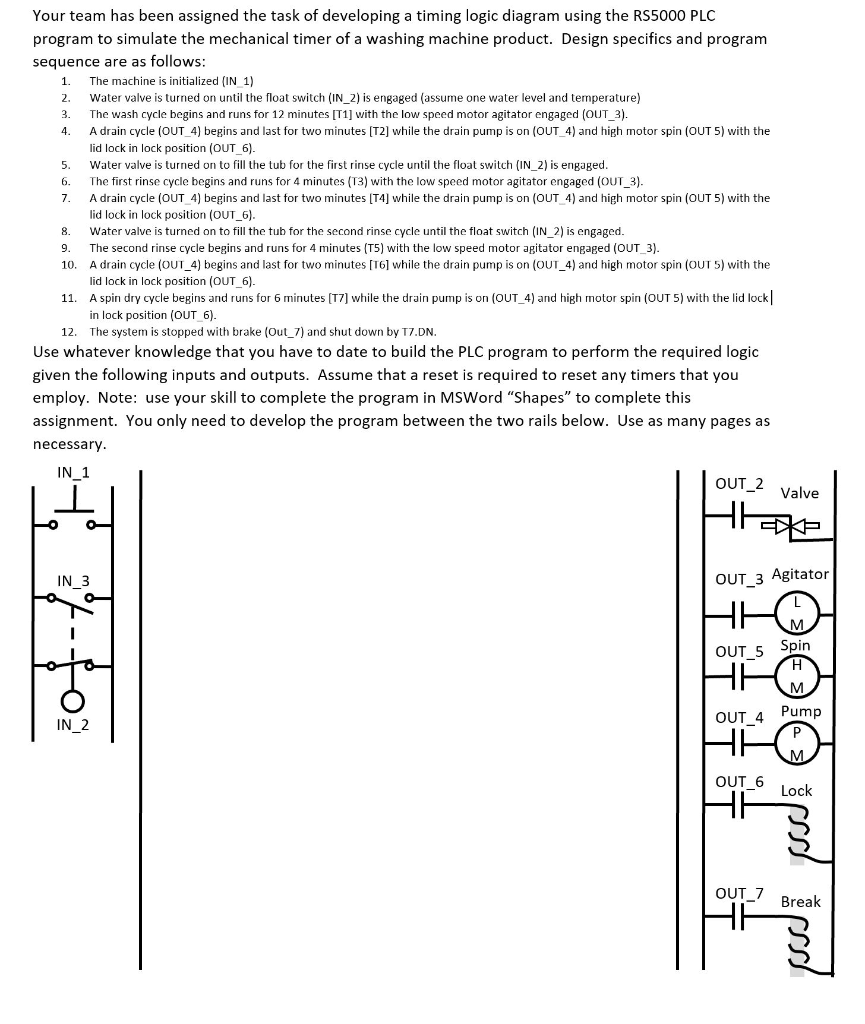
Your team has been assigned the task of developing a timing logic diagram using the RS5000 PLC program to simulate the mechanical timer of a washing machine product. Design specifics and program sequence are as follows: 1. The machine is initialized IN 1) 2. Water valve is turned on until the float switch (IN 2) is engaged (assume one water level and temperature) 3. The wash cycle begins and runs for 12 minutes [T1] with the low speed motor agitator engaged (OUT_3). 4. A drain cycle (OUT_4) begins and last for two minutes [T2] while the drain pump is on (OUT 4) and high motor spin (OUT 5) with the lid lock in lock position (OUT_6) 5. Water valve is turned on to fill the tub for the first rinse cycle until the float switch (IN_2) is engaged 6. The first rinse cycle begins and runs for 4 minutes (T3) with the low speed motor agitator engaged (OUT 3) 7. A drain cycle (OUT 4) begins and last for two minutes [T4] while the drain pump is on (OUT_4) and high motor spin (OUT 5) with the lid lock in lock position (OUT 6) 8. Water valve is turned on to fill the tub for the second rinse cycle until the float switch (IN 2) is engaged 9. The second rinse cycle begins and runs for 4 minutes (T5) with the low speed motor agitator engaged (OUT 3) 10. A drain cycle (OUT_4) begins and last for two minutes [T61 while the drain pump is on (OUT 4) and high motor spin (OUT 5) with the lid lock in lock position (OUT_6) 11. A spin dry cycle begins and ns for 6 minutes T7] while the drain pump is on (OUT_4) and high motor spin (OUT 5) with the lid lock in lock position (OUT6) 12. The system is stopped with brake (Out 7) and shut down by T7.DN Use whatever knowledge that you have to date to build the PLC program to perform the required logic given the following inputs and outputs. Assume that a reset is required to reset any timers that you employ. Note: use your skill to complete the program in MSWord "Shapes" to complete this assignment. You only need to develop the program between the two rails below. Use as many pages as necessary IN 1 OUT_2 Valve IN 3 OUT 3 Agitator OUT 5 Spin OUT 4 Pump IN 2 OUT_6 Lock OUT_7 Break Your team has been assigned the task of developing a timing logic diagram using the RS5000 PLC program to simulate the mechanical timer of a washing machine product. Design specifics and program sequence are as follows: 1. The machine is initialized IN 1) 2. Water valve is turned on until the float switch (IN 2) is engaged (assume one water level and temperature) 3. The wash cycle begins and runs for 12 minutes [T1] with the low speed motor agitator engaged (OUT_3). 4. A drain cycle (OUT_4) begins and last for two minutes [T2] while the drain pump is on (OUT 4) and high motor spin (OUT 5) with the lid lock in lock position (OUT_6) 5. Water valve is turned on to fill the tub for the first rinse cycle until the float switch (IN_2) is engaged 6. The first rinse cycle begins and runs for 4 minutes (T3) with the low speed motor agitator engaged (OUT 3) 7. A drain cycle (OUT 4) begins and last for two minutes [T4] while the drain pump is on (OUT_4) and high motor spin (OUT 5) with the lid lock in lock position (OUT 6) 8. Water valve is turned on to fill the tub for the second rinse cycle until the float switch (IN 2) is engaged 9. The second rinse cycle begins and runs for 4 minutes (T5) with the low speed motor agitator engaged (OUT 3) 10. A drain cycle (OUT_4) begins and last for two minutes [T61 while the drain pump is on (OUT 4) and high motor spin (OUT 5) with the lid lock in lock position (OUT_6) 11. A spin dry cycle begins and ns for 6 minutes T7] while the drain pump is on (OUT_4) and high motor spin (OUT 5) with the lid lock in lock position (OUT6) 12. The system is stopped with brake (Out 7) and shut down by T7.DN Use whatever knowledge that you have to date to build the PLC program to perform the required logic given the following inputs and outputs. Assume that a reset is required to reset any timers that you employ. Note: use your skill to complete the program in MSWord "Shapes" to complete this assignment. You only need to develop the program between the two rails below. Use as many pages as necessary IN 1 OUT_2 Valve IN 3 OUT 3 Agitator OUT 5 Spin OUT 4 Pump IN 2 OUT_6 Lock OUT_7 Break
Step by Step Solution
There are 3 Steps involved in it

Get step-by-step solutions from verified subject matter experts