

Question: Z ao PROBLEM 4 (35 PTS) Wo Artificial neuron model. The membrane potential z is a sum of products do membrane action (input activations a;
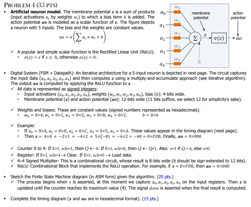
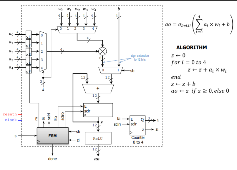
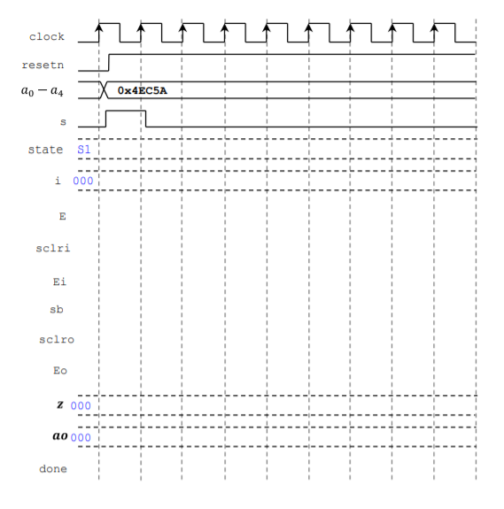
Z ao PROBLEM 4 (35 PTS) Wo Artificial neuron model. The membrane potential z is a sum of products do membrane action (input activations a; by weights wi) to which a bias term b is added. The potential potential action potential ao is modeled as a scalar function of z. The figure depicts W 01 a neuron with 5 inputs. The bias and the weights are constant values. W2 ao = 0 a X Wi + b a2 lo(z) W3 A popular and simple scalar function is the Rectified Linear Unit (ReLU): 83 0(z) = z if z 2 0, otherwise a(z) = 0. W4 b 24 Digital System (FSM + Datapath): An iterative architecture for a 5-input neuron is depicted in next page. The circuit captures the input data (ao, , az, az, a.) and then computes z using a multiply-and-accumulate approach (see iterative algorithm). The output ao is computed by applying the ReLU function to z. All data is represented as signed integers: Input activations (ag, az, az, az, 24), weights (wo, W1, W2, W3, w), bias (b): 4-bits wide. Membrane potential (z) and action potential (ao): 12-bits wide (11 bits suffice, we select 12 for simplicity's sake). Weights and biases: These are constant values (signed numbers represented as hexadecimals). Wo = 0x4, W, = 0x1, W2 = 0x2, W3 = 0x8, W4 = 0x2. b=0x6 Example: If a, = 0x4, aq = 0xE, az = 0xC, az = 0x5, 24 = 0xA. These values appear in the timing diagram (next page). Then z = 4x4 + -2x1 + - 4x2 + 5x(-8) + -6x2 = -40 = 0xFD8. Finally, ao = 0x000 Counter 0 to 4: If E=1, sclr=1, then Q+0. If E=1, sclr=0, then Q+Q+1. Also: z=1 if Q = 4, else z=0. Register: If E=1, sclr=1+ Clear. If E=1, sclr=0 Load data. 4x4 Signed Multiplier: This is a combinational circuit, whose result is 8-bits wide (it should be sign-extended to 12 bits). RELU: Combinational Block that implements the ReLU operation. For example, if z = 0xF08, then ao = 0x000 Sketch the Finite State Machine diagram (in ASM form) given the algorithm. (20 pts.) The process begins when s is asserted, at this moment we capture 20, 21, az, 23, 24 on the input registers. Then z is updated until the counter reaches its maximum value (4). The signal done is asserted when the final result is computed. Complete the timing diagram (z and ao are in hexadecimal format). (15 pts.) Wo W1 W2 W3 W4 b ao ORLU Qi X Wi + b a xwe 0 1 2 3 4 do ai N 4 az 22 24 sign extension to 12 bits IM 0 1 sb ALGORITHM z+0 for i = 0 to 4 zz +a; X Wi end 2+2 + b ao + z if z > 0, else 0 12 12 + 12 E scir resetn clock sclri ED Eo sciro EiE Q Z 12 sclri sclr N sb FSM ReLU Counter 0 to 4 12 done ao clock resetn ao - 04 Ox 4EC5A S state si i 000 E sclri Ei sb sclro EO Z 000 ao 000 done Z ao PROBLEM 4 (35 PTS) Wo Artificial neuron model. The membrane potential z is a sum of products do membrane action (input activations a; by weights wi) to which a bias term b is added. The potential potential action potential ao is modeled as a scalar function of z. The figure depicts W 01 a neuron with 5 inputs. The bias and the weights are constant values. W2 ao = 0 a X Wi + b a2 lo(z) W3 A popular and simple scalar function is the Rectified Linear Unit (ReLU): 83 0(z) = z if z 2 0, otherwise a(z) = 0. W4 b 24 Digital System (FSM + Datapath): An iterative architecture for a 5-input neuron is depicted in next page. The circuit captures the input data (ao, , az, az, a.) and then computes z using a multiply-and-accumulate approach (see iterative algorithm). The output ao is computed by applying the ReLU function to z. All data is represented as signed integers: Input activations (ag, az, az, az, 24), weights (wo, W1, W2, W3, w), bias (b): 4-bits wide. Membrane potential (z) and action potential (ao): 12-bits wide (11 bits suffice, we select 12 for simplicity's sake). Weights and biases: These are constant values (signed numbers represented as hexadecimals). Wo = 0x4, W, = 0x1, W2 = 0x2, W3 = 0x8, W4 = 0x2. b=0x6 Example: If a, = 0x4, aq = 0xE, az = 0xC, az = 0x5, 24 = 0xA. These values appear in the timing diagram (next page). Then z = 4x4 + -2x1 + - 4x2 + 5x(-8) + -6x2 = -40 = 0xFD8. Finally, ao = 0x000 Counter 0 to 4: If E=1, sclr=1, then Q+0. If E=1, sclr=0, then Q+Q+1. Also: z=1 if Q = 4, else z=0. Register: If E=1, sclr=1+ Clear. If E=1, sclr=0 Load data. 4x4 Signed Multiplier: This is a combinational circuit, whose result is 8-bits wide (it should be sign-extended to 12 bits). RELU: Combinational Block that implements the ReLU operation. For example, if z = 0xF08, then ao = 0x000 Sketch the Finite State Machine diagram (in ASM form) given the algorithm. (20 pts.) The process begins when s is asserted, at this moment we capture 20, 21, az, 23, 24 on the input registers. Then z is updated until the counter reaches its maximum value (4). The signal done is asserted when the final result is computed. Complete the timing diagram (z and ao are in hexadecimal format). (15 pts.) Wo W1 W2 W3 W4 b ao ORLU Qi X Wi + b a xwe 0 1 2 3 4 do ai N 4 az 22 24 sign extension to 12 bits IM 0 1 sb ALGORITHM z+0 for i = 0 to 4 zz +a; X Wi end 2+2 + b ao + z if z > 0, else 0 12 12 + 12 E scir resetn clock sclri ED Eo sciro EiE Q Z 12 sclri sclr N sb FSM ReLU Counter 0 to 4 12 done ao clock resetn ao - 04 Ox 4EC5A S state si i 000 E sclri Ei sb sclro EO Z 000 ao 000 done
Step by Step Solution
There are 3 Steps involved in it

Get step-by-step solutions from verified subject matter experts