

Question: Zoom in to see question clearly. Need Help. Given the code excerpt below: #include #include int main() { DDRD = OxFF: PORTD=0x00; // setup PWM
Zoom in to see question clearly.
Need Help.
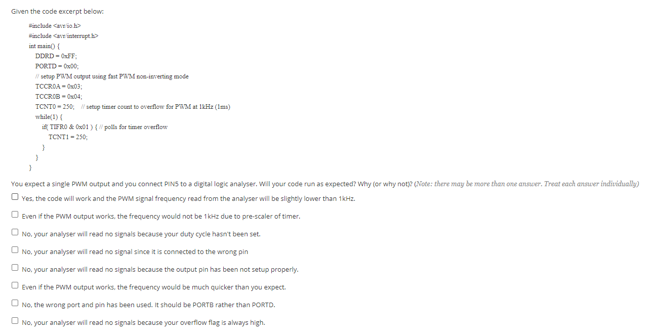
Given the code excerpt below: #include
Step by Step Solution
There are 3 Steps involved in it

Get step-by-step solutions from verified subject matter experts