

By observing that the circuit of 7-51 (a) is an inverting Schmitt trigger (introduced in Problem
Question:
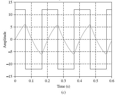
By observing that the circuit of 7-51 (a) is an inverting Schmitt trigger (introduced in Problem 5.58), argue that the capacitor voltage and the op amp’s output are correctly shown in Fig. 7-51(c).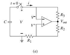
Data from Problem 5.58
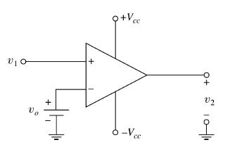
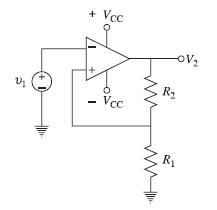
The op amp of Fig. 5-30 compares the input signal v1 with an independent reference level v0, forcing the op amp into high saturation (if v1 > v0) or low saturation (if v1 0). Let the reference level be set up by the output of the op amp through the voltage divider R1/(R1 + R2) as shown in Fig. 5-62(a) with R1 = 2R2. Assume saturation levels of ±15. Given v1(t) = 10(sin 20πt + sin 30πt) and v2(0) = 15 V, sketch the output voltage v2(t). The circuit is called an inverting Schmitt trigger.
Data from figure 5-30
Data from figure 5-62
Step by Step Answer:

This question has not been answered yet.
You can Ask your question!

Schaum S Outline Of Electric Circuits
ISBN: 9781260011968
7th Edition
Authors: Mahmood Nahvi, Joseph Edminister
