

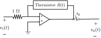
The following op-amp circuit is used to measure the changes of temperature in a system (Figure 2.20).
Question:
vo(t) = ˆ’R(t)vi(t)
Suppose that the temperature in the system changes cyclically after t = 0, so that
R(t) = [1 + 0.5 cos(20Ï€ t)]u(t).
Let the input be vi(t) = 1 volt.
(a) Assuming that the switch closes at t0 = 0 sec., use MATLAB to plot the output voltage vo(t) for 0 ‰¤ t ‰¤ 0.2 sec. in time intervals of 0.01 sec.
(b) If the switch closes at t0 = 50 msec., plot the output voltage vo1(t) for 0 ‰¤ t ‰¤ 0.2 sec. in time-intervals of 0.01 sec.
(c) Use the above results to determine if this system is time invariant. Explain.
Figure 2.20:
Fantastic news! We've Found the answer you've been seeking!
Step by Step Answer:
a The output voltage when the switch closes at t 0 is v o t Rt ut 1 05 cos20 t ut The ini...View the full answer

Answered By
GERALD KAMAU
non-plagiarism work, timely work and A++ work
6+ Reviews
11+ Question Solved
Related Book For 
Question Posted:
