

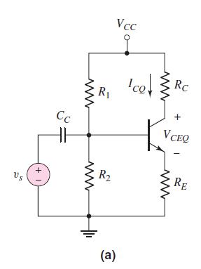
Consider a common-emitter circuit with the configuration shown in Figure 5.54(a). Assume a bias voltage of (V_{C
Question:
Consider a common-emitter circuit with the configuration shown in Figure 5.54(a). Assume a bias voltage of \(V_{C C}=3.3 \mathrm{~V}\) and assume the transistor current gain is in the range \(100 \leq \beta \leq 160\). Design the circuit such that the nominal \(Q\)-point is in the center of the load line and that the \(Q\)-point values do not vary by more than \(\pm 3\) percent. Determine appropriate values for \(R_{1}\) and \(R_{2}\).
Figure 5.54(a):-
Fantastic news! We've Found the answer you've been seeking!
Step by Step Answer:

Answered By
Anum Naz
Lecturer and researcher with 10+ years of experience teaching courses in both undergraduate and postgraduate levels. Supervised 17 BA theses, 07 MA theses, and 1 Ph.D. dissertations. Edited and co-authored 2 monographs on contemporary trends in political thought. Published over articles in peer-reviewed journals.
11+ Reviews
52+ Question Solved
Related Book For 

Microelectronics Circuit Analysis And Design
ISBN: 9780071289474
4th Edition
Authors: Donald A. Neamen
Question Posted:
