

For the circuit in Figure 10.40(a), the transistor parameters are (k_{n}^{prime}=) (80 mu mathrm{A} / mathrm{V}^{2}, k_{p}^{prime}=40
Question:
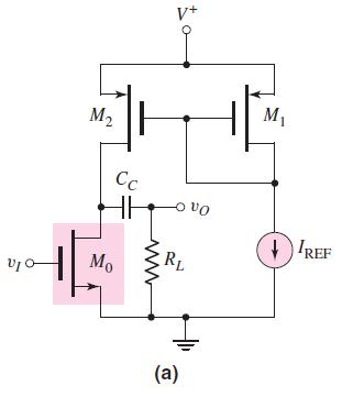
For the circuit in Figure 10.40(a), the transistor parameters are \(k_{n}^{\prime}=\) \(80 \mu \mathrm{A} / \mathrm{V}^{2}, k_{p}^{\prime}=40 \mu \mathrm{A} / \mathrm{V}^{2}, V_{T N}=0.8 \mathrm{~V}, V_{T P}=-0.6 \mathrm{~V}, \lambda_{n}=0.015 \mathrm{~V}^{-1}\), and \(\lambda_{p}=0.02 \mathrm{~V}^{-1}\). Also, assume \((W / L)_{o}=20\) and \((W / L)_{1}=\) \((W / L)_{2}=35\). The circuit parameters are \(V^{+}=5 \mathrm{~V}\) and \(I_{\mathrm{REF}}=200 \mu \mathrm{A}\).
(a) Determine the \(g_{m}\) and \(r_{o}\) parameters of each transistor.
(b) Determine the open-circuit small-signal voltage gain.
(c) Determine the value of \(R_{L}\) that results in a voltage gain of one-half the open-circuit value.
Figure 10.40(a):-
Step by Step Answer:


Microelectronics Circuit Analysis And Design
ISBN: 9780071289474
4th Edition
Authors: Donald A. Neamen
