

For the circuit shown in Figure P5.61, the bias voltages are changed to (V^{+}=3 mathrm{~V}) and (V^{-}=-3
Question:
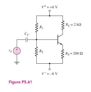
For the circuit shown in Figure P5.61, the bias voltages are changed to \(V^{+}=3 \mathrm{~V}\) and \(V^{-}=-3 \mathrm{~V}\).
(a) Design a bias-stable circuit for \(\beta=120\) such that \(V_{C E Q}=2.8 \mathrm{~V}\). Determine \(I_{C Q}, R_{1}\), and \(R_{2}\).
(b) If the resistors \(R_{1}\) and \(R_{2}\) vary by \(\pm 5\) percent, determine the range in \(I_{C Q}\) and \(V_{C E Q}\). Plot the various \(Q\)-points on the load line.
Step by Step Answer:

This question has not been answered yet.
You can Ask your question!
Related Book For 

Microelectronics Circuit Analysis And Design
ISBN: 9780071289474
4th Edition
Authors: Donald A. Neamen
Question Posted:
