

The BiCMOS circuit shown in Figure P11.82 is equivalent to a pnp bipolar transistor with an infinite
Question:
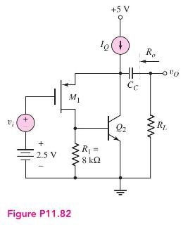
The BiCMOS circuit shown in Figure P11.82 is equivalent to a pnp bipolar transistor with an infinite input impedance. The bias current is \(I_{Q}=0.5 \mathrm{~mA}\). The MOS transistor parameters are \(V_{T P}=-0.5 \mathrm{~V}, K_{p}=0.7 \mathrm{~mA} / \mathrm{V}^{2}\), and \(\lambda=0\), and the BJT parameters are \(\beta=180, V_{B E}\) (on) \(=0.7 \mathrm{~V}\), and \(V_{A}=\infty\).
(a) Sketch the small-signal equivalent circuit.
(b) Calculate the small-signal parameters for each transistor.
(c) Determine the small-signal voltage gain \(A_{v}=v_{o} / v_{i}\) for (i) \(R_{L}=10 \mathrm{k} \Omega\) and (ii) \(R_{L}=100 \mathrm{k} \Omega\).
Step by Step Answer:

This question has not been answered yet.
You can Ask your question!
Related Book For 

Microelectronics Circuit Analysis And Design
ISBN: 9780071289474
4th Edition
Authors: Donald A. Neamen
Question Posted:
