

The circuit and transistor parameters for the circuit shown in Figure P11.39 are (V^{+}=5 mathrm{~V}, V^{-}=-5 mathrm{~V},
Question:
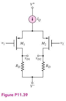
The circuit and transistor parameters for the circuit shown in Figure P11.39 are \(V^{+}=5 \mathrm{~V}, V^{-}=-5 \mathrm{~V}, I_{Q}=0.15 \mathrm{~mA}, R_{D}=30 \mathrm{k} \Omega, V_{T P}=-0.5 \mathrm{~V}\), \(K_{p}=0.12 \mathrm{~mA} / \mathrm{V}^{2}\), and \(\lambda=0\). The output resistance of the current source is \(R_{o}=4 \mathrm{M} \Omega\).
(a) Determine \(v_{D 1}-v_{D 2}\) for (i) \(v_{1}=+0.05 \mathrm{~V}, v_{2}=-0.05 \mathrm{~V}\) and (ii) \(v_{1}=+0.10 \mathrm{~V}, v_{2}=-0.10 \mathrm{~V}\).
(b) Determine the change in \(v_{D 2}\) as the inputs change (i) from \(v_{1}=v_{2}=0\) to \(v_{1}=0.10 \mathrm{~V}\) and \(v_{2}=-0.10 \mathrm{~V}\), and (ii) from \(v_{1}=v_{2}=0\) to \(v_{1}=1.10 \mathrm{~V}\) and \(v_{2}=0.90 \mathrm{~V}\).
Step by Step Answer:


Microelectronics Circuit Analysis And Design
ISBN: 9780071289474
4th Edition
Authors: Donald A. Neamen
