

The circuit in Figure P3.52 is another configuration used to switch an LED on and off. The
Question:
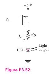
The circuit in Figure P3.52 is another configuration used to switch an LED on and off. The transistor parameters are \(V_{T P}=-0.6 \mathrm{~V}, k_{p}^{\prime}=40 \mu \mathrm{A} / \mathrm{V}^{2}\), and \(\lambda=0\). The diode cut-in voltage is \(V_{\gamma}=1.6 \mathrm{~V}\). Design \(R_{D}\) and the transistor width-to-length ratio such that \(I_{D}=15 \mathrm{~mA}\) for \(V_{I}=0 \mathrm{~V}\) and \(V_{S D}=0.20 \mathrm{~V}\).
Fantastic news! We've Found the answer you've been seeking!
Step by Step Answer:

Answered By
Joan Gakii
I'm a meticulous professional writer with over five years writing experience. My skill set includes
- Digital Content,
- Interpersonal Communication,
- Web Content and academic Writing,
- Proofreading,
- Editing,
- Project Management, and
- Public Relations.
7+ Reviews
12+ Question Solved
Related Book For 

Microelectronics Circuit Analysis And Design
ISBN: 9780071289474
4th Edition
Authors: Donald A. Neamen
Question Posted:
