

The full-wave rectifier circuit shown in Figure 2.5 (a) in the text is to deliver (0.2 mathrm{~A})
Question:
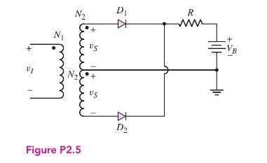
The full-wave rectifier circuit shown in Figure 2.5 (a) in the text is to deliver \(0.2 \mathrm{~A}\) and \(12 \mathrm{~V}\) (peak values) to a load. The ripple voltage is to be limited to \(0.25 \mathrm{~V}\). The input signal is \(120 \mathrm{~V}\) (rms) at \(60 \mathrm{~Hz}\). Assume diode cut-in voltages of \(0.7 \mathrm{~V}\).
(a) Determine the required turns ratio of the transformer.
(b) Find the required value of the capacitor.
(c) What is the PIV rating of the diode?
Figure 2.5:-
Fantastic news! We've Found the answer you've been seeking!
Step by Step Answer:

Answered By
FREDRICK MUSYOKI
Professional Qualities:
Solution-oriented.
Self-motivated.
Excellent problem-solving and critical thinking skills.
Good organization, time management and prioritization.
Efficient troubleshooting abilities.
Tutoring Qualities:
I appreciate students as individuals.
I am used to tailoring resources for individual needs.
I can integrate IT into student's lessons.
I am good at explaining concepts.
I am able to help students progress.
I have a wide curriculum knowledge.
1+ Reviews
10+ Question Solved
Related Book For 

Microelectronics Circuit Analysis And Design
ISBN: 9780071289474
4th Edition
Authors: Donald A. Neamen
Question Posted:
