

Question: A beam problem under the pure bending moment is solved using five rectangular finite elements, as shown in the figure. Assume (E=200 mathrm{GPa}) and (v=0.3)
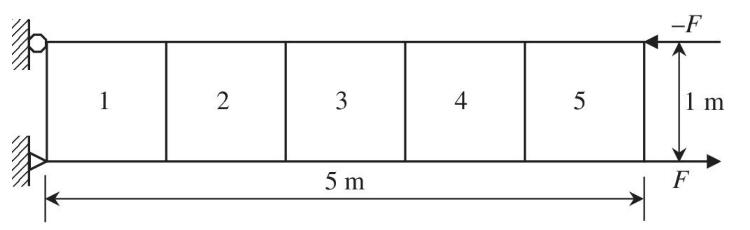
A beam problem under the pure bending moment is solved using five rectangular finite elements, as shown in the figure. Assume \(E=200 \mathrm{GPa}\) and \(v=0.3\) are used. The thickness of the beam is \(0.01 \mathrm{~m}\). In order to simulate pure bending moment, two opposite forces \(F= \pm\) \(100,000 \mathrm{~N}\) are applied at the end of the beam. Using a commercial FE program, calculate strains in the beam along the bottom surface. Draw graphs of \(\varepsilon_{x x}\) and \(\gamma_{x y}\) with the \(x\)-axis being the beam length. Compare the numerical results with the elementary beam theory. Provide an explanation for the differences, if any. Is the rectangular element stiff or soft compared to the CST element?
Normally, a commercial finite element program provides stress and strain at the nodes of the element by averaging the stresses computed in the adjacent elements. Thus, you may use nodal displacement data from FE code to calculate strains along the bottom surface of the element. Calculate the strains at about ten points in each element for plotting purposes. Make sure that the commercial program uses the standard Lagrange shape function.
Repeat the above procedure when an upward vertical force of \(200,000 \mathrm{~N}\) is applied at the tip of the beam. Use boundary conditions similar to the clamped boundary conditions of a cantilevered beam.
1 2 3 5 m 4 -F 5 1 m F
Step by Step Solution
There are 3 Steps involved in it

Get step-by-step solutions from verified subject matter experts