

Consider the single-line diagram of a power system shown in Figure 3.42 with equipment ratings given below:
Question:
Consider the single-line diagram of a power system shown in Figure 3.42 with equipment ratings given below:
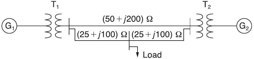
\[ \begin{array}{ll} \text { Generator } G_{1}: & 50 \mathrm{MVA},13.2\mathrm{kV}, x=0.15 ho u \\ \text { Generator } G_{2}: & 20 \mathrm{MVA},13.8\mathrm{kV}, x=0.15 ho u \\ \text { three-phase } \Delta-\mathrm{Y} \text { transformer } T_{1}: & 80 \mathrm{MVA},13.2\Delta / 165 \mathrm{Y} \mathrm{kV}, X=0.1 ho u \\ \text { three-phase Y- } \Delta \text { transformer } T_{2}: & 40 \mathrm{MVA}, 165 \mathrm{Y} /13.8\Delta \mathrm{kV}, X=0.1 ho u \\ \text { Load: } & 40 \mathrm{MVA},0.8\mathrm{PF} \text { lagging, operating at } 150 \mathrm{kV}\end{array}\]
Choose a base of 100 MVA for the system and $132-\mathrm{kV}$ base in the transmission-line circuit. Let the load be modeled as a parallel combination of resistance and inductance. Neglect transformer phase shifts.
Draw a per-phase equivalent circuit of the system showing all impedances in per unit.
FIGURE 3.42:-
Step by Step Answer:

This question has not been answered yet.
You can Ask your question!


Power System Analysis And Design
ISBN: 9781111425777
5th Edition
Authors: J Duncan Glover, Mulukutla S Sarma, Thomas Overbye
