

Figure 7.43 shows a liquid-level system in which two tanks have hydraulic capacitances (C_{1}) and (C_{2}), respectively.
Question:
Figure 7.43 shows a liquid-level system in which two tanks have hydraulic capacitances \(C_{1}\) and \(C_{2}\), respectively. The volume flow rate into tank 1 is \(q_{\mathrm{i}}\). The liquid flows from tank 1 to tank 2 through a valve of linear resistance \(R_{1}\) and leaves tank 2 through a valve of linear resistance \(R_{2}\). The density \(ho\) of the liquid is constant.
a. Derive the differential equations in terms of the liquid heights \(h_{1}\) and \(h_{2}\). Write the equations in matrix form.
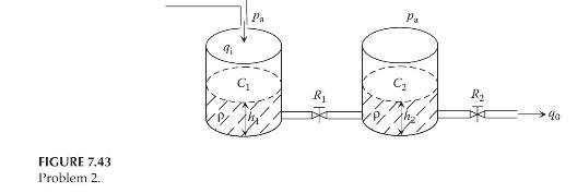
b. Assume that the volume flow rate \(q_{\mathrm{i}}\) is the input and the liquid heights \(h_{1}\) and \(h_{2}\) are the outputs. Determine the state-space form of the system.
c. Construct a Simulink block diagram to find the outputs \(h_{1}(t)\) and \(h_{2}(t)\) of the liquid-level system. Assume that \(ho=1000 \mathrm{~kg} / \mathrm{m}^{3}, g=9.81 \mathrm{~m} / \mathrm{s}^{2}\), \(C_{1}=0.15 \mathrm{~kg} \cdot \mathrm{m}^{2} / \mathrm{N}, C_{2}=0.25 \mathrm{~kg} \cdot \mathrm{m}^{2} / \mathrm{N}, R_{1}=R_{2}=100 \mathrm{~N} \cdot \mathrm{s} /\left(\mathrm{kg} \cdot \mathrm{m}^{2}\right)\), and initial liquid heights \(h_{1}(0)=1 \mathrm{~m}\) and \(h_{2}(0)=0 \mathrm{~m}\). The volume flow rate \(q_{\mathrm{i}}\) is a step function with a magnitude of 0 before \(t=0 \mathrm{~s}\) and a magnitude of \(0.25 \mathrm{~m}^{3} / \mathrm{s}\) after \(t=0 \mathrm{~s}\).
Step by Step Answer:


Modeling And Analysis Of Dynamic Systems
ISBN: 9781138726420
3rd Edition
Authors: Ramin S. Esfandiari, Bei Lu
