

Question: For the circuit in Figure 317, (a) Formulate node-voltage equations. (b) Solve for the output voltage O using R1 =R4 =2 k and R2 =R3
For the circuit in Figure 3–17,
(a) Formulate node-voltage equations.
(b) Solve for the output voltage υO using R1 =R4 =2 kΩ and R2 =R3 =4 kΩ.
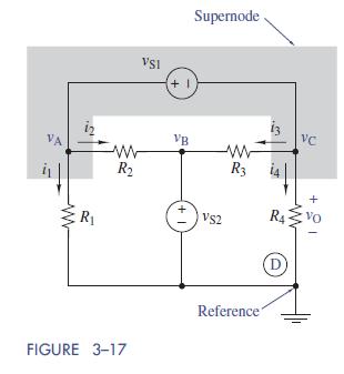
Supernode VSI +1 VC VB ww VA ww 12 R ww R +1 R3 +1 ww R4 VS2 D FIGURE 3-17 Reference
Step by Step Solution
There are 3 Steps involved in it
1 Expert Approved Answer
Step: 1 Unlock

Question Has Been Solved by an Expert!
Get step-by-step solutions from verified subject matter experts
Step: 2 Unlock
Step: 3 Unlock