

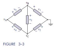
Question: The reference node and node voltages in the bridge circuit of Figure 33 are A =5V, B = 10 V, and C = 3 V.
The reference node and node voltages in the bridge circuit of Figure 3–3 are υA =5V,
υB = 10 V, and υC = −3 V. Find the element voltages
VB V3 VA VA FIGURE 3-3 VC
Step by Step Solution
There are 3 Steps involved in it
1 Expert Approved Answer
Step: 1 Unlock

Question Has Been Solved by an Expert!
Get step-by-step solutions from verified subject matter experts
Step: 2 Unlock
Step: 3 Unlock