

Figure 3.39 shows a oneline diagram of a system in which the three-phase generator is rated (300
Question:
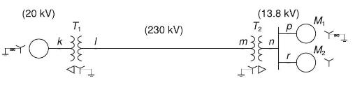
Figure 3.39 shows a oneline diagram of a system in which the three-phase generator is rated \(300 \mathrm{MVA}, 20 \mathrm{kV}\) with a subtransient reactance of 0.2 per unit and with its neutral grounded through a \(0.4-\Omega\) reactor. The transmission line is \(64 \mathrm{~km}\) long with a series reactance of \(0.5 \Omega / \mathrm{km}\). The three-phase transformer \(T_{1}\) is rated \(350 \mathrm{MVA}, 230 / 20 \mathrm{kV}\) with a leakage reactance of 0.1 per unit. Transformer \(T_{2}\) is composed of three single-phase transformers, each rated \(100 \mathrm{MVA}, 127 / 13.2 \mathrm{kV}\) with a leakage reactance of 0.1 per unit. Two \(13.2-\mathrm{kV}\) motors \(M_{1}\) and \(M_{2}\) with a subtransient reactance of 0.2 per unit for each motor represent the load. \(M_{1}\) has a rated input of 200 MVA with its neutral grounded through a \(0.4-\Omega\) current-limiting reactor. \(M_{2}\) has a rated input of 100 MVA with its neutral not connected to ground. Neglect phase shifts associated with the transformers. Choose the generator rating as base in the generator circuit and draw the positive-sequence reactance diagram showing all reactances in per unit.
Step by Step Answer:

This question has not been answered yet.
You can Ask your question!


Power System Analysis And Design
ISBN: 9781305632134
6th Edition
Authors: J. Duncan Glover, Thomas Overbye, Mulukutla S. Sarma
