

Question: Figure P4-80 shows two circuits using the same transistor connected in different ways. The transistor has a (beta) of 90 and a (V) (gamma) of
Figure P4-80 shows two circuits using the same transistor connected in different ways. The transistor has a \(\beta\) of 90 and a \(V\) \(\gamma\) of \(0.7 \mathrm{~V}\). Find the current gain of each circuit \(i_{\mathrm{C}} / i_{\mathrm{B}}\) for the common emitter and \(i_{\mathrm{C}} / i_{\mathrm{E}}\) for the common base configuration. Then compute the input resistance of each circuit, \(R_{\mathrm{IN}}=v_{\mathrm{IN}} / i\) \({ }_{\mathrm{N}}\). Check your answers using Multisim. Comment on the possible uses for each configuration. For the common base configuration, assume that the transistor is in the active mode and that KCL and the current gain relationships are valid, even though the currents are flowing opposite of the normal directions.
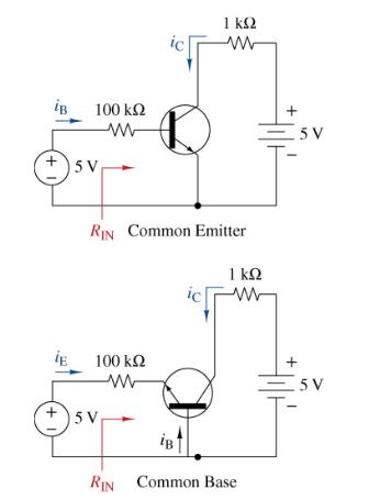
iB +1 +1 100 5V ww RIN Common Emitter 100 ww 5V 1 www 1 ww ich iB RIN Common Base 5 V 5V
Step by Step Solution
3.45 Rating (155 Votes )
There are 3 Steps involved in it
Examine the common emitter circuit first and assume it is in the active mode We have the following r... View full answer

Get step-by-step solutions from verified subject matter experts