

Question: In Problem 9.1 and Figure 9.17, let (765 mathrm{kV}) be replaced by (500mathrm{kV}), keeping the rest of the data to be the same. Problem 9.1
In Problem 9.1 and Figure 9.17, let \(765 \mathrm{kV}\) be replaced by \(500\mathrm{kV}\), keeping the rest of the data to be the same.
Problem 9.1
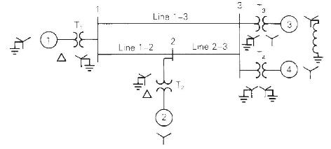
The single-line diagram of a three-phase power system is shown in Figure 9.17 . Equipment ratings are given as follows:
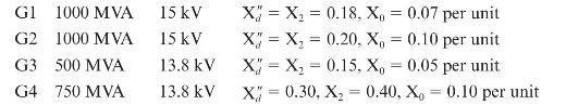
Synchronous generators:
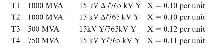
Transformers:
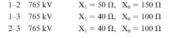
Transmission lines:
The inductor connected to Generator 3 neutral has a reactance of 0.05 per unit using generator 3 ratings as a base. Draw the zero-, positive-, and negative-sequence reactance diagrams using a \(1000-\mathrm{MVA}, 765-\mathrm{kV}\) base in the zone of line 1-2. Neglect the \(\Delta-Y\) transformer phase shifts.
G1 1000 MVA G2 1000 MVA G3 500 MVA G4 750 MVA 15 kV 15 kV 13.8 kV 13.8 kV X = X = 0.18, X = 0.07 per unit X = X = 0.20, X, = 0.10 per unit X = X = 0.15, X, = 0.05 per unit X = 0.30, X = 0.40, X, 0.10 per unit =
Step by Step Solution
3.52 Rating (165 Votes )
There are 3 Steps involved in it

Get step-by-step solutions from verified subject matter experts