Question:
Select a station-class metal-oxide surge arrester from Table 13.2 for the high-voltage side of a three-phase 400 MVA, \(345-\mathrm{kV}\) Y/13.8-kV \(\Delta\) transformer. The maximum \(60-\mathrm{Hz}\) operating voltage of the transformer under normal operating conditions is 1.03 per unit. The high-voltage windings of the transformer have a BIL of \(1300 \mathrm{kV}\) and a solidly grounded neutral. A minimum protective margin of 1.4 per unit based on a \(10-\mathrm{kA}\) impulse current wave cresting in \(0.5 \mu \mathrm{s}\) is required. Additional considerations for the selection of metal-oxide surge arresters are given in reference.
Table 13.2
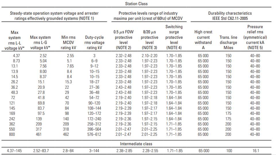
Transcribed Image Text:
Steady-state operation system voltage and arrester ratings effectively grounded systems (NOTE 1) Max system rms L-L voltage kV* 4.37 8.73 13.1 13.9 14.5 26.2 36.2 48.3 72 121 145 169 242 362 550 800 4.37-145 Max system rms L-G voltage KV* 2.52 5.04 7.56 8.00 8.37 15.1 20.9 27.8 41.8 69.8 83.7 97.5 139 209 317 461 2.52-83.7 Min rms MCOV rating kV 2.55 5.1 7.65 8.4 8.4 15.3 22 29 42 70 84 98 140 209 318 462 2.8-84 Duty-cycle rms voltage rating kv 3 6-9 9-12 10-15 10-15 18-27 27-36 36-48 54-72 90-120 108-144 120-172 172-240 258-312 396-564 576-612 3-144 Station Class Protective levels range of industry maxima per unit (crest of 60hz) of MCOV 0.5 s FOW protective level (NOTE 2) 2.32-2.48 2.33-2.48 2.33-2.48 2.33-2.48 2.33-2.48 2.33-2.48 2.43-2.48 2.43-2.48 2.19-2.40 2.19-2.40 2.19-2.39 2.19-2.39 2.19-2.36 2.19-2.36 2.01-2.47 2.01-2.47 8/20 s protective level (NOTE 3) 2.38-2.85 2.10-2.20 1.70-1.85 1.97-2.23 1.70-1.85 1.97-2.23 1.70-1.85 1.97-2.23 1.97-2.23 1.97-2.23 1.97-2.23 1.97-2.23 1.97-2.18 1.97-2.18 1.97-2.17 1.97-2.17 Intermediate class. Switching surge protective level (NOTE 4) 1.64-1.84 1.64-1.84 1.64-1.84 1.97-2.15 1.64-1.84 1.97-2.15 1.71-1.85 2.01-2.25 1.71-1.85 2.01-2.25 1.71-1.85 2.28-2.55 1.70-1.85 1.70-1.85 1.70-1.85 1.70-1.85 1.70-1.85 1.64-1.84 1.71-1.85 Durability characteristics IEEE Std C62.11-2005 High crest current withstand A 65 000 65 000 65 000 65 000 65 000 65 000 65 000 65 000 65 000 65 000 65 000 65 000 65 000 65 000 65.000 65 000 65 000 Trans. line: discharge Miles 150 150 150 150 150 150 150 150 150 150 150 175 175 200 200 200 100 Pressure relief rms (symmetrical) current KA (NOTE 5) 40-80 40-80 40-80 40-80 40-80 40-80 40-80 40-80 40-80 40-80 40-80 40-80 40-80 40-80 40-80 40-80 16.1


