

The circuit in Figure P16-14 shows a power line distribution and an intermediate substation and a final
Question:
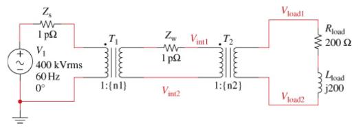
The circuit in Figure P16-14 shows a power line distribution and an intermediate substation and a final user substation. The source \(\mathbf{V}_{S}\) generates and steps up the voltage to \(400 \mathrm{kV}\) (rms), 60-Hz power. This power line is routed to an intermediate substation which steps down the voltage to \(33 \mathrm{kV}\) (rms). Finally at the user site, a second step-down transformer brings the voltage to \(220 \mathrm{~V}\) (rms). Assume the source impedance \(Z_{\mathrm{S}}\) and the wire impedance \(Z_{\mathrm{W}}\) to be negligible ( \(1 \mathrm{p} \Omega\) ). The load impedance is \(Z_{\mathrm{L}}=200+j 200 \Omega\).
(a) Find the turns ratio \(n\) for each transformer if they are considered ideal.
(b) Find the complex power \(S_{\mathrm{L}}\) delivered to the load.
(c) Find the load power factor pf.
(d) Verify your answers using Multisim.
Step by Step Answer:
a b c d The first transformer steps the voltage dow...View the full answer


The Analysis And Design Of Linear Circuits
ISBN: 9781119913023
10th Edition
Authors: Roland E. Thomas, Albert J. Rosa, Gregory J. Toussaint
