

Question: The periodic triangular wave in Figure P13-22 is applied to the (R L C) circuit shown in the figure. (a) Use the results in Figure
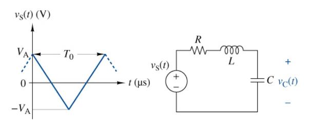
The periodic triangular wave in Figure P13-22 is applied to the \(R L C\) circuit shown in the figure.
(a) Use the results in Figure 13-4 in the text to find the Fourier coefficients of the input for \(V_{\mathrm{A}}=5 \mathrm{~V}\) and \(T_{\mathrm{O}}=\) \(400 \pi \mu \mathrm{s}\).
(b) Find \(T(s)=V_{\mathrm{C}}(s) / V_{\mathrm{S}}(s)\).
(c) Find the amplitude of the first five nonzero terms in the Fourier series for \(v_{C}(t)\) when \(R=1 \Omega, L=8 \mathrm{mH}\), and \(C=\) \(0.2 \mu \mathrm{F}\) What term in the Fourier series tends to dominate the response? Explain.
(d) Build the circuit but use a simple ac source. Do an ac sweep and verify why the circuit responds as it does. Multiply the input \(a_{n}\) at \(25 \mathrm{krad} / \mathrm{s}\) and verify that \(v_{\mathrm{C}}(t)\) is correct.
Vs(t) (V) -VA To 1 (us) Vs(1) R w roo L C vc(1)
Step by Step Solution
3.56 Rating (153 Votes )
There are 3 Steps involved in it
a b c d The Fourier coeffi... View full answer

Get step-by-step solutions from verified subject matter experts