

Question: The scheme shown in Figure may be viewed as a differential encoder (consisting of the modulo-2 adder and the 1-unit delay element) connected in cascade
The scheme shown in Figure may be viewed as a differential encoder (consisting of the modulo-2 adder and the 1-unit delay element) connected in cascade with a spec form of correlative coder consisting of the 1-unit delay element and summer). A single delay element is shown in Figure since it is common to both the differential encoder and the correlative coder in this differential encoder, a transition is represented by o and no transition by symbol 1.
(a) Find the frequency response and impulse response of the correlative coder part of the scheme shown in Figure.
(b) Show that this scheme may be used to convert the on-off representation of a binary sequence (applied to the input) into the bipolar representation of the sequence at output. You may illustrate this conversion by considering the sequence 010001101. For descriptions of on?off, bipolar, and differential encoding of binary sequences, see Section 3.7.
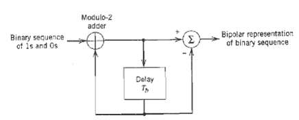
Modulo-2 adder Bipolar representation of binary sequence ) Binary sequence of 1s and Os Delay
Step by Step Solution
3.40 Rating (162 Votes )
There are 3 Steps involved in it
a The correlative coder has output Yn n1 Its impuls... View full answer

Get step-by-step solutions from verified subject matter experts
Document Format (1 attachment)
19-E-T-E-C-S (305).docx
120 KBs Word File