

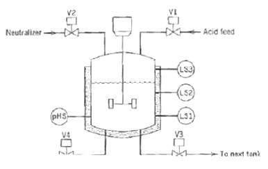
Question: Consider a neutralization system shown in figure, where a certain amount of acid feed is added to a tank, chemically treated, and then sent to
Consider a neutralization system shown in figure, where a certain amount of acid feed is added to a tank, chemically treated, and then sent to the next tank. Sensor pHS indicates whether or not the solution has the correct pH. When pHS is activated, the neutralization is complete. Level switches LS1, LS2, and LS3 are activated when the level in the tank is at or above a given Level. The neutralization process proceeds with the following steps:
(a) Initially, all the valves arc closed, the mixer is off, and the neutralization tank is empty.
(b) When the start button (not shown) is pressed, V1 opens and LS2 is activated. These actions till the tank with the solution to be neutralized.
(c) When the solution level rises above LS2, start mixer M. When the level drops below LS1, stop the mixer.
(d) Whenever the pH of the solution is too low, open V2 to add neutralizer.
(e) If the tank becomes full before the acid feed is neutralizer, indicated by the activation of LS3, close V2 to stop the inflow of neutralizer. Next, open V4 to reduce the liquid level to the point indicated by LS2; this solution will be reprocessed later. Then close V4 and proceed with step (d) again.
(f) When the pH of the solution is correct, close V2 and open ?V3 to drain the tank. When the tank is empty, indicated by the deactivation of LSI, close V3 and proceed with step (a). Draw information flow and adder logic diagrams and a sequential function chart.
-Acid feed Neutralizer (Ls3) (L52) L31 (pHS V3 Ta next tonk
Step by Step Solution
3.44 Rating (173 Votes )
There are 3 Steps involved in it
Information Flow Diagram Ladder Logi... View full answer

Get step-by-step solutions from verified subject matter experts
Document Format (1 attachment)
38-E-C-E-P-C (355).docx
120 KBs Word File