

Question: Figure a, shows a non-coherent receiver using a matched filter for the detection of a sinusoidal signal of known frequency but random phase, in the
Figure a, shows a non-coherent receiver using a matched filter for the detection of a sinusoidal signal of known frequency but random phase, in the presence o additive white Gaussian noise. An alternative implementation of this receiver is its mechanization in the frequency domain as a spectrum analyzer receiver, as in Figure b, where the correlator computes the finite time auto correlation function Rx(?) defined by show that the square-law envelope detector output sampled at time t = T in Figure a is twice the spectral output of the Fourier transformer sampled at frequency f = fc in Figure b.
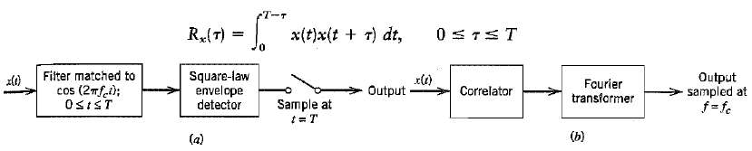
cT-T x(t)x(t + r) dt, R(T) 0. Filter matched to cos (2mf.i); Output sampled at f= fe Fourier transformer Square-law envelope detector Correlator Output Sample at t= T OSIST (b) (a)
Step by Step Solution
3.42 Rating (180 Votes )
There are 3 Steps involved in it
Let xt Acos2f t t 8 A cos2ft cos 6 Asin 2 ft sin The output of the squarelaw enve... View full answer

Get step-by-step solutions from verified subject matter experts
Document Format (1 attachment)
19-E-T-E-C-S (65).docx
120 KBs Word File