

Question: Figure shows an RLC circuit that is driven by an emf source of fixed amplitude m. Initially the circuit consists of one resistor of
Figure shows an RLC circuit that is driven by an emf source of fixed amplitude ξ m. Initially the circuit consists of one resistor of resistance R. one inductor of inductance L, and one capacitor of capacitance C, and the driving frequency matches the natural frequency. Then switches S1, S2, S3, and S4 are closed, in that order. The closings bring in capacitors identical to the first one or resistors identical to the first one. Let ξ m = 12.0V, C = 2.00μF, L = 2.00 mH, and R = 12.0 O.
(a) Fill in the first blank column of the following table with the values of the equivalent capacitance C e q of the circuit after each switch closing. Similarly, fill in the other columns with values for
(b) The resonance frequency f,
(c) The equivalent resistance R e q,
(d) The impedance Z, and
(e) The current amplitude 1. (Avoid rounding off the numbers until all calculations are finished.)
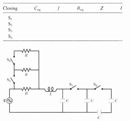
Rey Ce Closing S, S, S, S4 C.
Step by Step Solution
3.24 Rating (168 Votes )
There are 3 Steps involved in it
Reading carefully we note that the driving frequency of the source is permanently ... View full answer

Get step-by-step solutions from verified subject matter experts
Document Format (1 attachment)
2-P-O-E-O (97).docx
120 KBs Word File