

Figure shows the block diagram of a zero-crossing detector for demodulating an FM signal, its consist of
Question:
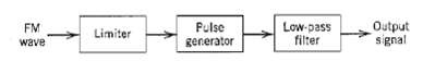
Figure shows the block diagram of a zero-crossing detector for demodulating an FM signal, its consist of a limiter, a pulse generator for producing a short pulse at each zero-crossing of the input, and a low-pass filter for extracting the modulating wave.
(a) Show that the instantaneous frequency of the input FM signals is proportional to the number of zero crossings in the time interval t ? (T1/2) to t + (T1/2), divided by T1, Assume that the modulating is essentially constant during this time interval.
(b) Illustrate the operation of this demodulator, using the saw-tooth wave of Figure as the modulating wave.
Fantastic news! We've Found the answer you've been seeking!
Step by Step Answer:
a In the time interval tT2 to t T2 assume there are n ...View the full answer

Answered By
Hamza Amjad
Currently I am student in master degree program.from last two year I am tutring in Academy and I tought many O/A level student in home tution.
3+ Reviews
10+ Question Solved
Related Book For 

Question Posted:
