

Question: In Figure a potential difference V = 100 V is applied across a capacitor arrangement with capacitances C1 = 10.0F, C2 = 5.00F, and C3
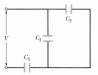
In Figure a potential difference V = 100 V is applied across a capacitor arrangement with capacitances C1 = 10.0μF, C2 = 5.00μF, and C3 = 15.0μF. What are?
(a) Charge q3,
(b) Potential difference V3, and
(c) Stored energy U3for capacitor 3,
(d) q1
(e) V1 and
(f) U1 for capacitor 1, and
(g) q2,
(h) V2, and
(l) U2 for capacitor 2?
V C G Co
Step by Step Solution
★★★★★
3.46 Rating (179 Votes )
There are 3 Steps involved in it
1 Expert Approved Answer
Step: 1 Unlock

a The potential difference across C the same as across C is ... View full answer
Question Has Been Solved by an Expert!
Get step-by-step solutions from verified subject matter experts
Step: 2 Unlock
Step: 3 Unlock
Document Format (1 attachment)
2-P-E-C-D (302).docx
120 KBs Word File