

Question: Determine the differential-mode gain, common-mode gain, differential-mode input resistance, and common-mode input resistance for the circuit of Fig. 3.45 with I TAIL = 20 µA,
Determine the differential-mode gain, common-mode gain, differential-mode input resistance, and common-mode input resistance for the circuit of Fig. 3.45 with ITAIL= 20 µA, RTAIL=
10 MΩ, RC = 100 kΩ, and VEE = VCC = 5 V. Neglect rb, ro, and rμ. Calculate the CMRR. Check with SPICE and use SPICE to investigate the effects of adding nonzero rb and finite VA as given in Fig. 2.30.
Fig. 3.45:
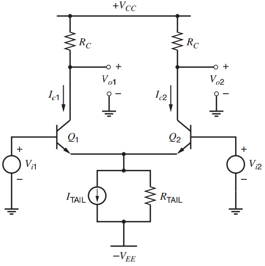
Fig. 2.30:
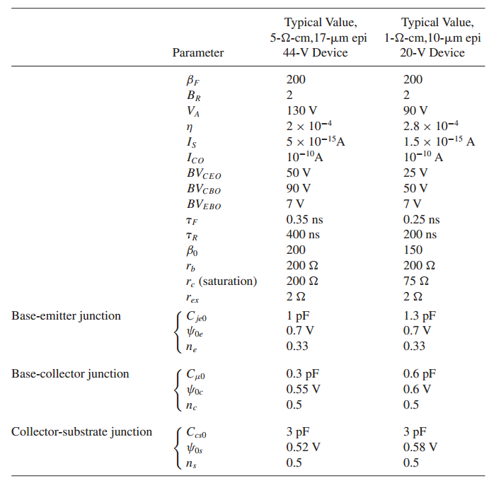
+Vcc RC RC Vo2 Vo1 I2 Q2 Q1 Vi2 Vi1 RTAIL ITAIL -VEE ypcal Value, ypical Value, 5-2-cm,17-m epi 1-2-cm,10-m epi 44-V Device 20-V Device Parameter 200 200 Bf 2 2 VA 130 V 90 V 2 x 10⁻⁴ 5 x 10-15A 10-1A 2.8 x 10⁻⁴ 1.5 x 10⁻¹⁵ A 10-10 A Is Ico BVCEO BV BVEBO 50 V 25 V 90 V 50 V 7V 0.35 ns 0.25 ns TF 400 ns 200 ns TR Bo 200 150 200 2 200 2 r re (saturation) 200 2 75 2 rex 1.3 pF C je0 1 pF 0.7 V Base-emitter junction 0.7 V 0.33 0.33 ne 0.3 pF 0.6 pF Yoc Base-collector junction 0.55 V 0.6 V 0.5 0.5 3 pF 3 pF Ces0 Vos Collector-substrate junction 0.52 V 0.58 V 0.5 0.5 ns
Step by Step Solution
3.49 Rating (156 Votes )
There are 3 Steps involved in it
We first neglect the DC current thro... View full answer

Get step-by-step solutions from verified subject matter experts
Document Format (2 attachments)
1528_605d88e1a96d8_686774.pdf
180 KBs PDF File
1528_605d88e1a96d8_686774.docx
120 KBs Word File