

Question: Repeat Problem 9.43 for the circuit in Fig. 9.64 with C in = 4 pF. Inject the test sources on the left-hand side of the
Data from Prob. 9.43:
A technique that allows the return ratio to be simulated using SPICE without disrupting the dc operating point is shown in Fig. 8.60 and explained in Problem 8.33.
(a) Use that technique to simulate the return ratio for the op amp from Problem 9.21 connected in a non-inverting unity-gain configuration for f = 1 kHz, 100 kHz, 10 MHz, and 1 GHz.
(b) Use that technique to plot the magnitude and phase of the return ratio. Determine the unity-gain frequency for the return ratio and the phase and gain margins.
Figure 8.60:
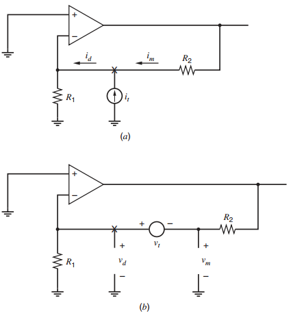
Figure 9.64:
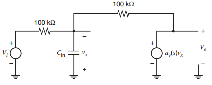
R2 R1 (a) R2 V yt R4 (b) 100 k2 100 k2 V. Cin a,(s)v,
Step by Step Solution
3.49 Rating (162 Votes )
There are 3 Steps involved in it
a b The unitygain frequency is 8 kHz The phase margin is 90 The gain margin is 40dB RETURN ... View full answer

Get step-by-step solutions from verified subject matter experts
Document Format (2 attachments)
1528_605d88e1c48b0_687061.pdf
180 KBs PDF File
1528_605d88e1c48b0_687061.docx
120 KBs Word File