

Figure P17.10 shows a simplified configuration of a steam generation system. In combustor R-1102, the following reaction
Question:
Figure P17.10 shows a simplified configuration of a steam generation system. In combustor R-1102, the following reaction takes place: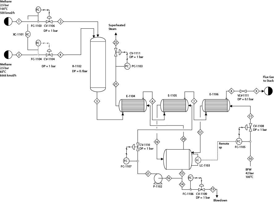
![]()
Complete conversion of the fuel gas in R-1102 can be assumed. Flue gas from the combustor goes to the superheater, E-1104, followed by the steam generator, E- 1105. Finally, the flue gas flows through the economizer, E- 1006, before going to the stack. The bfw flows through E- 1006 before reaching the steam drum, V-1104. A portion of the bottom steam from the steam drum goes to the blowdown. The other portion goes to pump P-1102 and then to E-1105. The differential pressure across P-1102 should be equal to the pressure drop across CV-1110 and E-1105. The exit stream from E-1105 returns to V-1104. The pressure drop in V-1104 can be neglected. The generated steam gets superheated in E-1104 before leaving the unit. The degree of superheat in E-1104 is 100°C. Assume Stream 19 is 99% vapor. V-1104 may be considered to be adiabatic.
1. First, develop a steady-state model of this process. Simulate E-1104, E- 1105, and E-1106 as “rigorous” heat exchangers. (Note that the pressure drop across the heat exchangers is not provided in the problem statement since it should be determined by the detailed design of these exchangers.) Implement two design specifications. The first design specification manipulates the flow of bfw, Stream 10, to ensure that the temperature of Stream 8 is 150°C to avoid “cold-end” corrosion. The other design specification manipulates the flowrate of the circulating water, Stream 16, so that the flowrate of the blowdown stream, Stream 14, is 1% of the bfw feed, Stream 10.
2. Develop a dynamic model of this system. For E-1104, E-1105, and E-1106, provide the shell-side and tube-side volumes and the metal mass of each side. Heat loss to the environment for all equipment can be neglected. Size V-1104 following the heuristics in Chapter 11. Figure P17.10 shows that the air flowrate to R-1102 is regulated by a ratio controller, XC-1101, that maintains the molar ratio between fuel and air at the steady-state value. LC-1103 is cascaded with FC-1105 to maintain the level of V-1104. Information on cascaded loops and ratio controllers is available in Chapter 18. Tune the controllers with various methods and rules and compare their performance by simulating a 20% step increase in the fuel flowrate. Performance of all the controllers should be considered, especially that of LC-1103 and PC-1103.
3. Compare the performance of various integrator algorithms for this problem.
4. In Part (b), the performance of all the controllers has been considered for a 20% step increase in the fuel flowrate. Now consider simultaneously a 20% step decrease in the fuel flowrate as well as a step increase to the set point of PC-1103 by 0.5 bar. Did the same set(s) of controller tuning parameters that performed satisfactorily before again perform satisfactorily? If not, why? If the tuning parameters need to be changed, ensure that you are satisfied with the performance of the control system for both Part (b) of this problem and the current problem.
Step by Step Answer:


Analysis Synthesis And Design Of Chemical Processes
ISBN: 9780134177403
5th Edition
Authors: Richard Turton, Joseph Shaeiwitz, Debangsu Bhattacharyya, Wallace Whiting
