

This diagram shows a thin slice of metal of thickness t and width d. The metal slice
Question:
This diagram shows a thin slice of metal of thickness t and width d. The metal slice is in a magnetic field of flux density B and carries a current I, as shown.
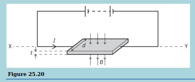
a. Copy the diagram and mark:
i. the side of the slice that becomes negative because of the Hall effect
ii. where a voltmeter needs to be placed to measure the Hall voltage.
b. Derive an expression for the Hall voltage in terms of I, B, t, the number density of the charge carriers n in the metal and the charge e on an electron.
c. Given that I = 40 mA, d = 9.0 mm, t = 0.030 mm, B = 0.60 T, e = 1.6 × 10⁻¹⁹ C and n = 8.5 × 1028 m–3, calculate:
i. The mean drift velocity v of the free electrons in the metal
ii. The Hall voltage across the metal slice
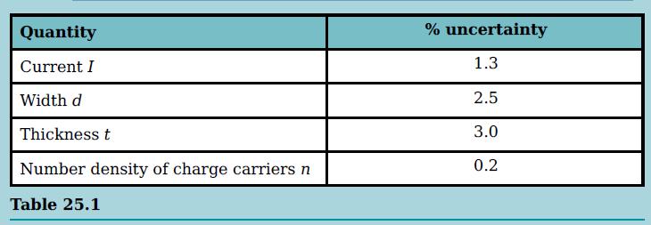
iii. The percentage uncertainty in the mean drift velocity v of the electrons, assuming the percentage uncertainties in the quantities are as shown.
d. i. Explain why, in terms of the movement of electrons, the Hall voltage increases when I increases.
ii. A Hall probe used to determine the magnetic flux density of a magnetic field uses a thin slice of a semiconductor rather than metal. Explain why a semiconductor is used.
e. Explain why, when the slice of metal is rotated about the horizontal axis XY, the Hall voltage varies between a maximum positive value and a maximum negative value.
Step by Step Answer:
a i The side of the slice that becomes negative because of the Hall effect is on the right side of t...View the full answer


Cambridge International AS And A Level Physics Coursebook
ISBN: 9781108859035
3rd Edition
Authors: David Sang, Graham Jones, Gurinder Chadha, Richard Woodside
