

Question: a. Example 13-1: Batch Reactor with an Exothermic Reaction Wolfram 1. Adiabatic Case: Use Wolfram to see whether you can find a trajectory that is
a. Example 13-1: Batch Reactor with an Exothermic Reaction
Wolfram
1. Adiabatic Case: Use Wolfram to see whether you can find a trajectory that is ready “to ignite” and whose trajectory looks like a “cobra” ready to strike, .
2. Heat Exchange Case:
(1) Vary UA and Ta1 and suggest conditions at which runaway might occur.
(2) Use the plot of Qr and Qg as a function of time to describe and explain what you see as you vary Ta1 and NA0 from their maximum to minimum values.
3. Write three conclusions on what you found in experiments (i) and (ii).
Polymath
4. How much time would it take to achieve 90% conversion for adiabatic operation if the reaction were started on a very cold day where the initial temperature was 20°F? (Methanol won’t freeze at this temperature.)
5. Now, consider that a heat exchanger is added to the reactor for the propylene oxide reaction; the parameters are: CA0 = 1 lb-mol/ft3, V = 1.2 ft3, (ΣNiCPi = 403 Btu°R), neglect ΔCP, UA = 0.22 Btu/°R/s, and Ta = 498 K. Plot and analyze the trajectories X, T, Qg, and Qr as a function of time.
Example 13-1
It is still winter, and although you were hoping for a transfer to the plant in the tropical southern coast of Florida, you unfortunately are still the engineer of the CSTR from
Example 12-3, in charge of the production of propylene glycol.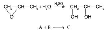
You are considering the installation of a new, attractive-looking, glass-lined 1000-dm3 CSTR, and you decide to make a quick check of the reaction kinetics and maximum adiabatic temperature. You have a stylish, nicely decorated and instrumented 40-dm3 (~10 gal) stirred batch reactor you ordered from a company. You charge (i.e., fill) this reactor with 4 dm3 (~1 gal) of ethylene oxide, 4 dm3 (~1 gal) of methanol, and 10 dm3 (~2.5 gal) of water containing 0.1 wt % H2SO4. For safety reasons, the reactor is located on a boating pier on the banks of Lake Walloon (you don’t want the entire plant to be destroyed if the reactor explodes). At this time of year in northern Michigan, the initial temperature of all materials is 276 K (3°C). We have to be careful here! If the reactor temperature increases above 350 K (77°C), a
secondary, more exothermic reaction will take over, causing runaway and subsequent explosion, similar to what happened in the T2 Laboratory plant explosion in Florida. Although you requested obtaining the data for this reaction from the Jofostan national research laboratory, the purchasing department decided to save money and buy it off the Internet. The values it purchased are![]()
Prof. Dr. Sven Köttlov objected to this Internet purchase and said that it should be recorded that he is skeptical of these parameter values. The initial concentrations of pure ethylene oxide and methanol are 13.7 and 24.7 mol/dm3, respectively. Consequently, the initial number of moles added to the reactor are A: Ethylene oxide:NA0=(13.7 mol/dm3)(4 dm3)=54.8 molB: Water:NB0=(55.5 mol/dm3)(10 dm3)=555 molM: Methanol:NM=(24.7 mol/dm3)(4 dm3)=98.8 mol
The sulfuric acid catalyst takes up negligible space, so the total volume is 18 dm3, while the data and the reaction-rate law are given in Example 12-3. We are going to carry out two scenarios:
(1) to learn how fast the temperature rises and how long it takes to reach 350 K for adiabatic operation,
(2) how long would it take to reach 345 K if we added a heat exchanger.
1. Adiabatic Operation: Plot conversion and temperature X and T as a function of time for adiabatic operation. How many minutes should it take the mixture inside the reactor to reach a conversion of 51.5%? What is the corresponding adiabatic temperature?
2. Heat Exchange: Plot the temperature and conversion as a function of time when a heat exchanger is added. The product of the overall heat transfer coefficient and exchange surface area is UA = 10 cal/s/K with Ta1 = 290 K and the coolant rate is 10 g/s, and it has a heat capacity of 4.16 cal/g/K.
Example 12-3
Propylene glycol is produced by the hydrolysis of propylene oxide: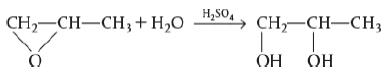
Ethylene oxide (C3H6O) is a 3-carbon compound with an Oxygen group connecting the first 2 carbons. This ethylene oxide and water react in the presence of sulfuric acid (H2SO4). The H plus and OH minus ions of the water molecule combine with the first and the second carbons of the oxide to form propylene glycol (C3H8O2). Over 900 million pounds of propylene glycol were produced in 2010 and the selling price was approximately $0.80 per pound. Propylene glycol makes up about 25% of the major derivatives of propylene oxide. The reaction takes place readily at room temperature when catalyzed by sulfuric acid. You are the engineer in charge of an adiabatic CSTR producing propylene glycol by this method. Unfortunately, the reactor is beginning to leak, and you must replace it. (You told your boss several times that sulfuric acid was corrosive and that mild steel was a poor material for construction. He wouldn’t listen.) There is a nice-looking, bright, shiny overflow CSTR of 300-gal capacity standing idle in Professor Köttlov’s storage shed at his mountain vacation home. It is glass-lined, and you would like to
use it. We are going to work this problem in lbm, s, ft3, and lb-moles rather than g, mol, and m3 in order to give the reader more practice in working in both the English and metric systems. Why?? Many plants still use the English system of units. You are feeding 2500 lbm/h (43.04 lb-mol/h) of propylene oxide (P.O.) to the reactor. The feed stream consists of
(1) an equivolumetric mixture of propylene oxide (46.62 ft3/h) and methanol (46.62 ft3/h),
(2) water containing 0.1 wt % H2SO4. The volumetric flow rate of water is 233.1 ft3/h, which is 2.5 times the methanol–P.O. volumetric flow rate. The corresponding molar feed rates of methanol and water are 71.87 and 802.8 lb-mol/h, respectively. The water–propylene oxide–methanol mixture undergoes a slight decrease in volume upon mixing (approximately 3%), but you neglect this decrease in your calculations. The temperature of both feed streams is 58°F prior to mixing, but there is an immediate 17°F temperature rise upon mixing of the two feed streams caused by the heat of mixing. The entering temperature of all feed streams is thus taken to be 7°F (Figure E12-3.1).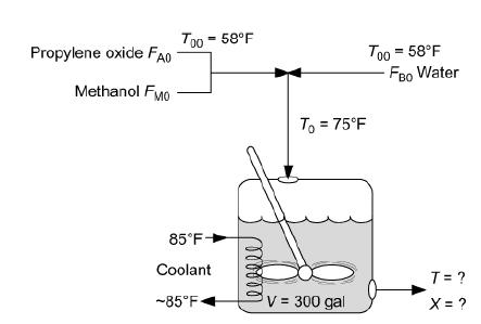
A CSTR is shown in which the following are marked: The input, here is propylene oxide (F subscript A0) and methanol (F subscript M0), belonging to the first feed stream. Water (F subscript B0), belongs to the second feed streams at 58 degrees Fahrenheit. The temperature, T subscript 0 increases to 75 degrees Fahrenheit when it enters the tank reactor, on mixing. The temperature of the coolant is approximately 85 degrees Fahrenheit. The volume of the fluid inside the reactor is 300 gallons. The output values of T and X are to be found. The Furusawa Engineering Team in Japan state that under conditions similar to those at which you are operating, the reaction is apparent first-order in propylene oxide concentration and apparent zero-order in excess of water with the specific reaction rate T. Furusawa, H. Nishimura, and T. Miyauchi, J. Chem. Eng. Jpn., 2, 95.
k = Ae–E/RT = 16.96 × 10¹² (e –32400/RT) h–1
The units of E are Btu/lb-mol and T is in °R. There is an important constraint on your operation. Propylene oxide is a rather low-boiling-point substance. With the mixture you are using, the company’s safety team feels that you cannot exceed an operating temperature of 125°F, or you will lose too much propylene oxide by vaporization through the vent system.
1. Can you use the idle CSTR as a replacement for the leaking one if it will be operated adiabatically?
2. If so, what will be the expected conversion of propylene oxide to glycol?
b. Example 13-2: Safety in Chemical Plants with Exothermic Runaway Reactions.
This is another Stop and Smell the Roses Simulation.
Wolfram
1. View the temperature trajectory for the base case and then describe how it changes when the charge (i.e., the amount initially in the reactor) is varied above and below the base case value.
2. Show the explosion would not have occurred for the triple production case if the heat exchanger had not failed.
3. Does it make any sense to plot the down time, (t2 – t1), versus time since the start of the reaction that the reactor fails, (t1) to identify regions where the explosion will and will not occur? Explain.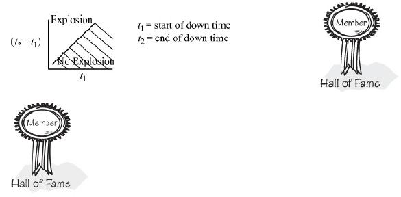
If it does make sense, please prepare such a plot; if not, explain why.
Choose another larger value of t1 and repeat. Continue in this manner to construct your plot.
4. Use Wolfram to find a value of NA0 below which no explosion would occur when all other variables remain as in the base case. Repeat for NB0.
5. Use Wolfram to find the value of NCp and also of UA, above which no explosion would occur.
6. Develop a set of guidelines as to how the reaction should be quenched should the cooling fail. Perhaps safe operation could be discussed using a plot of the length of the cooling failure, t2 – t1, as a function of the time at which the cooling failed, t1, for the different charges of ONCB.
7. Write a set of conclusions related to safety from your experiments in (i) and (v).
Polymath
8. Modify the Polymath code to show that no explosion would have occurred if the cooling was not shut off for the 9.04-kmol charge of ONCB, or if the cooling
was shut off for 10 minutes after 45 minutes of operation for the 3.17-kmol ONCB charge.
9. Find a set of parameter values that would cause the explosion to occur at exactly 12:18 A.M. For example, include the mass and heat capacities of the metal
reactor and/or make a new estimate of UA.
10. Finally, what if a 1/2-in. rupture disk rated at 800 psi had been installed and did indeed rupture at 800 psi (270°C)? Would the explosion still have occurred? Note: The mass flow rate varies with the cross-sectional area of the disk. Consequently, for the conditions of the reaction, the maximum mass flow rate out of the 1/2-in. disk can be found by comparing it with the mass flow rate of 830 kg/min of the 2-in. disk. Go to the Living Example Problems on the Web site and explore on your own the ONCB explosion described in Example 13-2. Explain what you would do to prevent an explosion of this type from ever occurring again while still operating at the triple production specified by management.
Example 13-2
Adapted from the problem by Ronald Willey, Seminar on a Nitroaniline Reactor Rupture. Prepared for SAChE, Center for Chemical Process Safety, American Institute of Chemical Engineers, New York (1994). Also see Process Safety Progress, vol. 20, no. 2 (2001), pp. 123–129. The values of ΔHRx and UA were estimated from the plant data of the temperature–time trajectory in the article by G. C. Vincent, Loss Prevention, 5, 46–52. A serious accident occurred at the Monsanto plant in Sauget, Illinois, on August 8, 1969, at 12:18 A.M. (see Figure E13-2.1). (Sauget (pop. 200) is the home of the 1988 Mon-Clar League Softball Champions.) The blast was heard as far as 10 mi away in Belleville, Illinois, where people were awakened from a deep sleep. The explosion occurred in a batch reactor that was used to produce nitroaniline from ammonia and o-nitrochlorobenzene (ONCB):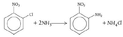
This reaction is normally carried out isothermally at 175°C and about 500 psi over a 24-hour period. The ambient temperature of the cooling water in the heat exchanger is 25°C. By adjusting the coolant flow rate, the reactor temperature could be maintained at 175°C. At the maximum coolant rate, the ambient temperature is 25°C throughout the heat exchanger. Also review the T2 Laboratories Safety Modules
(http://umich.edu/~safeche/assets/pdf/courses/Problems/344ReactionEngrModule(1)PS-T2.pdf).
Let me tell you something about the operation of this reactor. Over the years, the heat exchanger would fail from time to time, but the technicians would be “Johnny on the Spot” and run out and get it up and running within 10 minutes or so, and there was never any problem. It is believed that one day someone in management looked at the reactor and said, “It looks as if your reactor is only a third full and you still have room to add more reactants and to make more product and more money. How about filling it up to the top so we could triple production?” They did, and started the reactor up at 9:45 P.M. Around midnight the reactor exploded and the aftermath is shown in Figure E13-2.1. On the day of the accident, two changes in normal operation occurred.
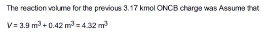
1. The reactor was charged with 9.044 kmol of ONCB, 33.0 kmol of NH3, and 103.7 kmol of H2O. Normally, the reactor is charged with 3.17 kmol of ONCB, 103.6 kmol of H2O, and 43 kmol of NH3. A decision was made to triple production.
Figure E13-2.1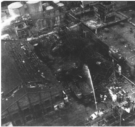
2. The reaction is normally carried out isothermally at 175°C over a 24-hour period. However, approximately 45 minutes after the reaction was started, cooling to the reactor failed, but only for 10 minutes, after which cooling was again up and running at the 55-minute mark. Cooling may have been halted for 10 minutes or so on previous occasions when the normal charge of 3.17 kmol of ONCB was used and no ill effects occurred. The reactor had a rupture disk designed to burst when the pressure exceeded approximately 700 psi. If the disk would have ruptured, the pressure in the reactor would have dropped, causing the water to vaporize, and the reaction would have been cooled (quenched) by the latent heat of vaporization.
1. Plot and analyze the temperature–time trajectory up to a period of 120 minutes after the reactants were mixed and brought up to 175°C (448K).
2. Show that all of the following three conditions had to have been present for the explosion to occur: (1) increased ONCB charge, (2) cooling stopped for 10 minutes at a time early in the reaction, and (3) relief-system failure.
Additional information: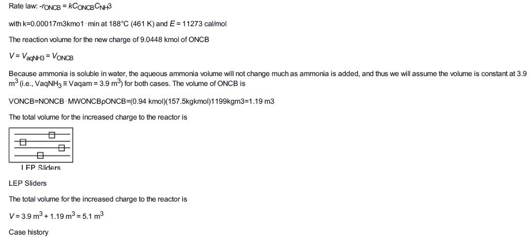
c. Example 13-3: Startup of a CSTR
Wolfram
1. What is the minimum coolant flow such that there is no upturn in temperature–concentration profile for Case 2 (Ti = 339 K, CAi = 0)?
2. Is it possible to prevent crossing of practical stability limit for Case 3 (Ti = 344 K, CAi = 2.26) by varying coolant temperature, coolant flow, or overall heat transfer coefficient? If so, which is the parameter and which should be varied to achieve that?
3. Use Wolfram to find initial temperatures and concentrations that will cause the temperature trajectory to exceed the practical stability limit, and then write a conclusion.
Polymath
4. Consider the case when CAi = 0.1 lb mol/ft3 and Ti = 150°F. What is the minimum coolant temperature such that the practical stability limit is not exceeded?
5. Describe what happens to the trajectories for an entering temperature of 70°F, an initial reactor temperature of 160°F, and an initial concentration of propylene oxide of 0.1 M.
6. Try various combinations of T0, Ti, and CAi, and report your results in terms of temperature– time trajectories and temperature concentration phase planes.
7. Find a set of conditions above which the practical stability limit will be reached or exceeded, and those conditions below which it will not.
8. Vary the coolant flow rate and compare with the base case given in Figures E13-3.1 to E13-3.4. Describe what you find and then write a conclusion.
COMSOL CSTR Startup
Go to the COMSOL hot button on the LEP Web site for Chapter 13 (http://www.umich.edu/~elements/6e/13chap/comsol_lep_tutorial.html) to access this
LEP in COMSOL.
9. Vary the tank volume between 1 and 5 m3 and describe the differences in the trajectories and the time to reach steady state and exceeding a practical stability limit of 360 K.
10. Use the base case parameters for the trajectory Ti = 340 K and Ci = 1400 mol/m3 to find the maximum feed temperature you can have that will not exceed the practical stability limit of 360 K?
11. Pick two operating parameters from ν0, Vtank, T0, Ta, mc, and UA to vary from minimum to maximum values, and describe what you find.
12. Vary the activation energy, EA, and discuss the effect of EA on the number of oscillations to reach steady state.
13. Write three conclusions from your COMSOL experiments (ix) through (xii).
Example 13.3
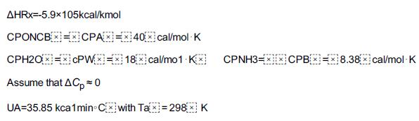
Again, we consider the production of propylene glycol (C) in a CSTR with a heat exchanger in Example 12-3. Initially there is only water, Cwi = 55.3 kmol/m3, at Ti = 297 K and 0.1 wt % H2SO4 in the 1.89 m3 reactor. The feed stream consists of 36.3 kmol/h of propylene oxide (A), 453.6 kmol/h of water (B) containing 0.1 wt % H2SO4, and 45.4 kmol/h of methanol A + B → C (M). The water coolant flows through the heat exchanger at a rate of 2.27 kg/s (453.6 kmol/h). The molar densities of pure propylene oxide (A), water (B), and methanol (M) are ρA0 = 14.8 kmol/m3, ρB0 = 55.3 kmol/ m3, and ρM0 = 24.7 kmol/ m3, respectively. Plot the temperature and concentration of propylene oxide as a function of time, and also the concentration of A as a function of temperature for different entering temperatures and initial concentrations of A in the reactor to learn whether the practical stability limit of 355 K is exceeded.
Additional information: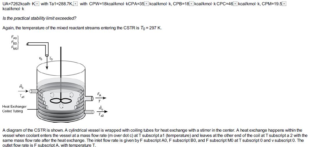
Figures E13-3.1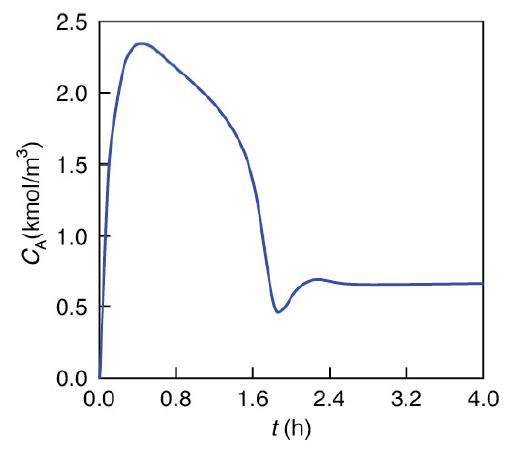
Figures E13-3.4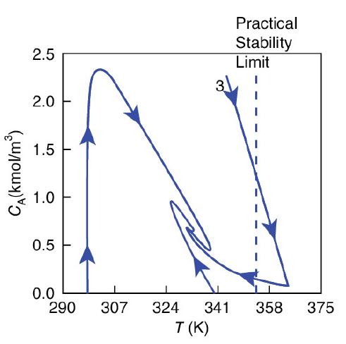
d. Example 13-4: LEP Semibatch
Wolfram
1. Use Wolfram to vary CB0 and describe how the maximum in CC varies.
2. List the slider variables that have virtually no effect on the temperature trajectory. Repeat for the concentration trajectory.
3. Which parameter, when varied, causes the graphs of T and Ta2 to overlap each other?
4. What is the minimum inlet temperature such that 100% conversion of A is still achieved?
5. Write three conclusions on what you found from your experiments (i) through (iv).
Polymath
6. At what times will the number of moles of C (NC = CCV) and the concentration of species C reach a maximum?
7. Are the times in part (i) that these maximums occur different, and if so, why? What would the X versus t and T versus t trajectories look like if the coolant rate were increased by a factor of 10? Why is the reaction time (252 seconds) so short?
8. Problem. Assume the surface area contacting the reacting fluid changes with time. The initial fluid volume in the reactor is 0.2 m3 and the inlet volumetric flow rate is 0.004 m3/s. Calculate the heat exchanger area as a function of time if the half-pipe jacket on page 684 is 0.5 m in diameter. Repeat for diameters of 1.0 and 0.25 m.
Example 13-4
The second-order saponification of ethyl acetate is to be carried out in a semibatch reactor shown schematically in Figure E13-4.1.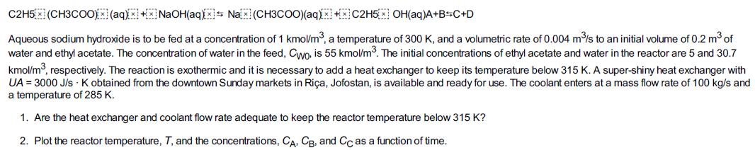
Additional information
Value for k from J. M. Smith, Chemical Engineering Kinetics, 3rd ed. New York: McGraw-Hill, 1981, p. 205. Note that ΔHRx and KC were calculated from values given in Perry’s Chemical Engineers’ Handbook, 6th ed. New York: McGraw-Hill, 1984, pp. 3–147.![k=0.39175x] exp[5472.7x) (1273-1T1]m3/kmol.s KC-103885.44/T AHRxoxx-79,076kj/kmol/k](https://dsd5zvtm8ll6.cloudfront.net/images/question_images/1697/8/6/4/43265335af0ad3c81697864431040.jpg)
A diagram shows a square-shaped vessel with a stirrer. It is closed except for two circular openings at the top. The water and sodium hydroxide is fed from the top. The concentration of the mixtures fed through the inlet are C subscript W0 and C subscript B0. The initial concentrations of ethyl acetate, water, and sodium hydroxide inside the vessel are marked as C subscript W i, C subscript A i, and C subscript B i. The vessel is connected to an inductor. The mass flow m dot subscript c is constant, while the temperature T subscript a 1 become T subscript a 2 after the reaction.
e. Example 13-5: LEP Multiple Reactions in a Semi batch Reactor
Wolfram
1. Assume a secondary reaction ignites when the reactor temperature reaches 450 K. Find the value (or combination thereof) of CA0 and ν0 above which the secondary reaction will ignite.
2. Vary CA0 and ν0 between their maximum and minimum values and describe how the concentration trajectories change and why they change the way they do.
3. Which parameter, when varied, results in equal concentration of A, B, and C at some point in time? What is the parameter value? Write two conclusions. Polymath
4. Vary the volumetric flow rate (between 24 0 5. Plot and analyze the trajectories of NA = CAV and NB = CBV for long times (e.g., t = 15 hours). What do you observe?
6. Can you show for long times that NA ≅ CA0ν0/k1A and NB ≅ CA0ν0/2k2B?
7. If species B is the desired product, how would you maximize NB?
Example 13-5
The series reactions 2A→k1A(1) B →k2B(2) 3C are catalyzed by H2SO4. All reactions are first order in the reactant concentration. However, Reaction
(1) is exothermic and Reaction
(2) is endothermic. The reaction is to be carried out in a semi batch reactor that has a heat exchanger inside with UA = 35000 cal/h · K and a constant exchanger temperature, Ta, of 298 K. Pure A enters at a concentration of 4 mol/dm3, a volumetric flow rate of 240 dm3/h, and a temperature of 305 K. Initially, there is a total of 100 dm3 of liquid in the reactor, which contains 1.0 mol/dm3 of A and 1.0 mol/dm3 of the catalyst H2SO4. The reaction rate is independent of the catalyst concentration. The initial temperature inside the reactor is 290 K.
1. Plot and analyze the species concentrations and reactor temperature as a function of time.
2. Analyze the results in (a) and comment on any maximums or minimums in the trajectories.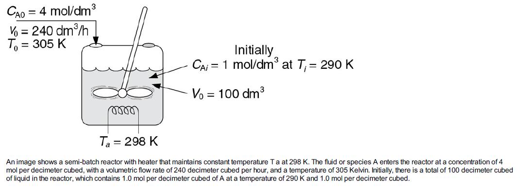
Additional information:
f. Example 13-6: LEP T2 Laboratories Explosion
Wolfram
This problem is a Stop and Smell the Roses Simulation. We need to spend more time than usual exploring this problem. First view the video
described on the Web site (http://umich.edu/~safeche/assets/pdf/courses/Problems/CRE/344ReactionEngrModule(1)PS-T2.pdf).
i. Vary the liquid volume, V0, and learn its effect on pressure profile. What is the critical value of V0 at which pressure shoots up?
ii. Which parameter will you vary such that concentration of B is always higher than concentration of C?
iii. Vary different parameters and check whether it is possible that the temperature limitation is reached before the pressure limitation.
iv. Find a value of the heat of reaction for the secondary reaction of diglyme, below which no explosion would have occurred.
v. Write a set of conclusions and of the lessons learned.
Polymath
vi. Review the safety module (http://umich.edu/~safeche/assets/pdf/courses/Problems/344ReactionEngineeringModule(2)PS050818.pdf ) and fill out the safety algorithm. Write a set of conclusions and the lessons learned.
vii.
(a) What did you learn from watching the video?
(b) Suggest how this reactor system should be modified and/or operated in order to eliminate any possibility of an explosion.
(c) Would you use backup cooling and, if so, how? (d) How could you learn whether a second reaction could be set in at a higher
temperature? Hint: See PRS R13.1 The Complete ARSST.
viii. Plot CA, CB, CC, P, and T as a function of time. Vary UA between 0.0 and 2.77 × 10⁶ J/h/K to find the
lowest value of UA that you observe a runaway to find the value of UA below which you would observe runaway. Describe the trends as you approach runaway. Did it occur over a very narrow range of UA values?
ix. Now let’s consider the actual operation in more detail. The reactor contents are heated from 300 K to 422 K at a rate of = 4 K/minute. At 422 K, the reaction rate is sufficient such that heating is turned off. The reactor temperature continues to rise because the reaction is exothermic, and, when the temperature reaches 455 K, the cooling water turns on and cooling is initiated. Model this situation for the case when UA = 2.77 × 10⁶ J/h/K and when UA = 0.
x. What is the maximum time in minutes that the cooling can be lost (UA = 0) starting at the time when the reactor temperature reaches 455 K so that the reactor will not reach the explosion point? The conditions are those of part (1) of this problem.
xi. Vary the parameters and operating conditions and describe what you find.
7. Download the Living Example Problem for Falling Off the Upper Steady State. Try varying the entering temperature, T0, between 80°F and 68°F, and plot the steady-state conversion as a function of T0. Vary the coolant rate between 10,000 and 400 mol/h. Plot conversion and
reactor temperature as a function of coolant rate.
8. Download the Living Example Problem. Vary the gain, kC, between 0.1 and 500 for the integral controller of the CSTR. Is there a lower value of kC that will cause the reactor to fall to the lower steady state or an upper value to cause it to become unstable? What would happen if T0
were to fall to 65°F or 60°F?
9. Download the Living Example Problem. Learn the effects of the parameters kC and τ1. Which combination of parameter values generates the least and greatest oscillations in temperature? Which values of kC and τ1 return the reaction to steady state the quickest?
10. SAChE. Go to the SAChE Web site (www.sache.org). On the left-hand menu, select “SaChe Products.” Select the “All” tab and go to the module titled: “Safety, Health and the Environment (S, H & E).” The problems are for KINETICS (i.e., CRE). There are some example problems marked K and explanations in each of the above S, H & E selections. Solutions to the problems are in a different section of the site. Specifically look at: Loss of Cooling Water (K-1), Runaway Reactions (HT-1), Design of Relief Values (D-2), Temperature Control and Runaway (K-4) and (K-5), and Runaway and the Critical Temperature Region (K-7). Go through the K problems and write a paragraph on what you have learned. Your instructor or department chair should have the username and password to enter the SAChE Web site in order to obtain the module with the problems.
Example 13-6
This example was coauthored by Professors Ronald J. Willey, Northeastern University, Michael B. Cutlip, University of Connecticut, and H. Scott Fogler, University of Michigan, and published in Process Safety Progress, 30, 1 (2011).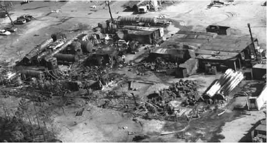
The aftermath of a deadly explosion at T2 Laboratories is shown in Figure E13-6.1. T2 Laboratories manufactured a fuel additive, methylcyclopentadienyl manganese tricarbonyl (MCMT), in a 2450-gal, high-pressure batch reactor utilizing a three-step batch process. (See
http://umich.edu/~safeche/assets/pdf/courses/CRE/344ReactionEngrModule(1)PS-T2.pdf.)
Step 1a. The liquid-phase metalation reaction between methylcyclopentadiene (MCP) and sodium in a solvent of diethylene glycol dimethyl ether (diglyme) to produce sodium methylcyclopentadiene and hydrogen gas is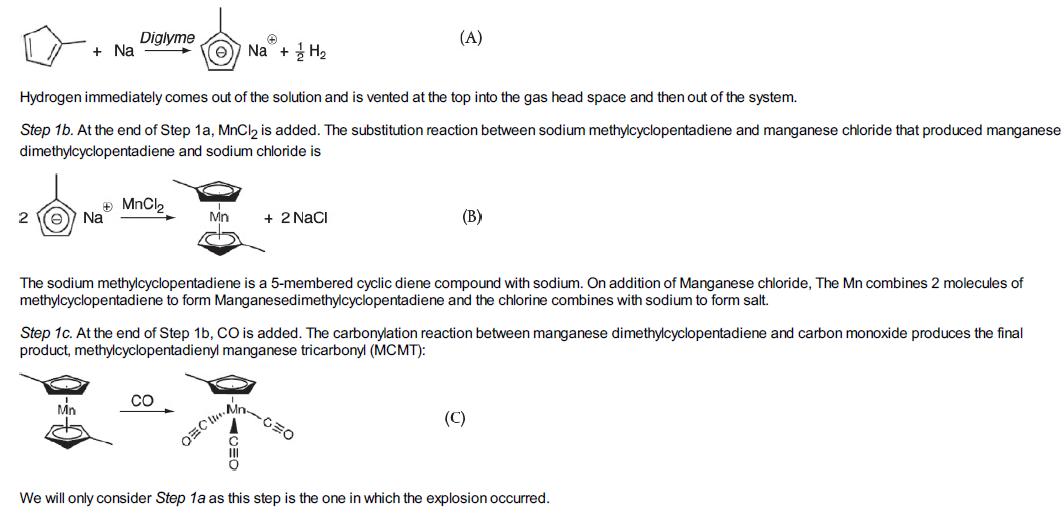
Procedure
First, solid sodium is mixed in the batch reactor with methylcyclopentadiene dimer and a solvent diethylene glycol dimethyl ether (diglyme). The batch reactor is then heated to about 422 K (300°F) with only slight reaction occurring during this heating process. On reaching 422 K, the heating is turned off, as the exothermic reaction is now proceeding, and the temperature continues to increase without further heating. When the temperature reaches 455.4 K (360°F), the operator initiates cooling using the evaporation of boiling water in the reactor jacket as the heat sink (Ta = 373.15 K; 212°F). Before reading further it might be helpful to view the Chemical Safety Board (CSB) video of the accident
(http://umich.edu/~safeche/courses/ChemicalReactionEngineering.html). It’s a really good video. What Happened On December 19, 2007, when the reactor reached a temperature of 455.4 K (360°F), the process operator could not initiate the flow of cooling water to the cooling
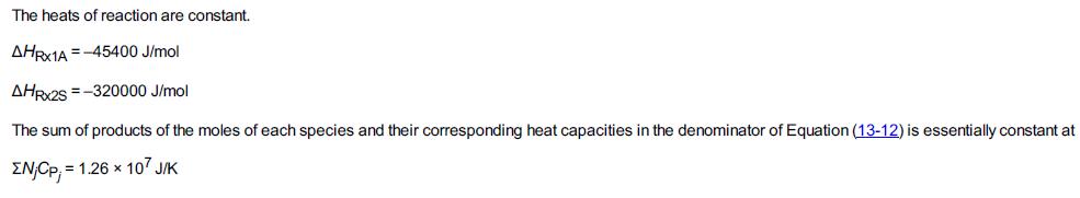
jacket shown in Figure E13-6.2. Thus, the expected cooling of the reactor was not available and the temperature in the reactor continued to rise. The pressure also increased as hydrogen continued to be produced at an increased rate, to the point that the reactor’s pressure control valve system on the 1-in. diameter hydrogen venting stream could no longer vent the gas and maintain the operating pressure at 50 psig (4.4 atm). As the temperature continued to increase further, a previously unknown exothermic secondary reaction of the decomposition of diglyme solvent, also catalyzed by sodium, accelerated rapidly.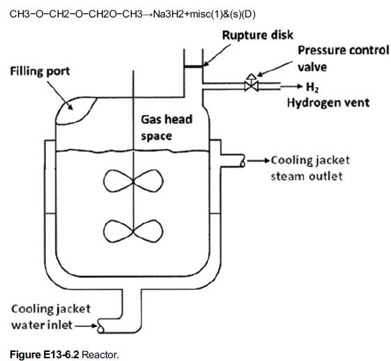
In the full reactor, the cooling jacket water inlet gives water for cooling the reactor and outlet is placed at the right side of reactor. The gas head space has a filling port at the left side and it has the vent with pressure control valve on the right side through which H2 is let out.
This reaction produced even more hydrogen, causing the pressure to rise even faster, eventually causing the rupture disk which was set at 28.2 atm absolute (400 psig), to break, in the 4-in. diameter relief line for H2. Even with the relief line open, the rate of production of H2 was now far greater than the rate of venting, causing the pressure to continue to increase to the point that it ruptured the reactor vessel initiating a horrific explosion. The T2 plant was completely leveled and four personnel lives were lost. Surrounding businesses were heavily damaged and additional injuries were sustained. I would like to emphasize again, before continuing with this example, it might be helpful to view the 9-minute Chemical Safety Board (CSB) video, which you can access directly from the CRE Web site (under YouTube videos), or you can read the supporting reports (http://www.csb.gov/videos/runaway-explosion-at-t2-laboratories/). Also review the T2 Laboratores Safety Modules (http://umich.edu/~safeche/assets/pdf/courses/Problems/344ReactionEngineeringModule(2)PS050818.pdf ).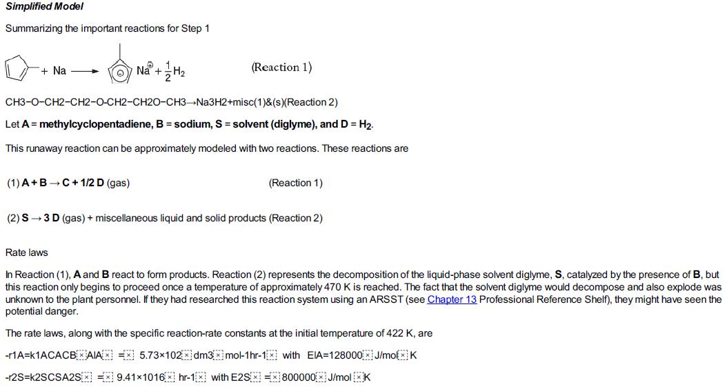
Assumptions
Assume that the liquid volume, V0, in the reactor remains constant at 4000 dm3 and that the vapor space, VH, above the reactor occupies 5000 dm3. Any gas, H2 (i.e.,D), that is formed by Reactions (1) and (2) immediately appears as an input stream FD to the head-space volume. The dissolved H2 and the vapor pressures for the liquid components in the reactor will be neglected. The initial absolute pressure within the reactor is 4.4 atm (50 psig). During normal operation, the H2 generated obeys the ideal gas law. The pressure control system on the H2 vent stream maintains the pressure, P, at 4.40 atm up to a flow of 11400 mol/hr. The reactor vessel will fail when the pressure exceeds 45 atm or the temperature exceeds 600 K.
Additional information:
UA = 2.77 x 10⁶ J hr–1 K–1. The concentrations in the reactor at the end of the reactor heating at 422 K are CA0 = 4.3 mol/dm3, CB0 = 5.1 mol/dm3, CI0 = 0.088 mol/dm3, and CS0 = 3 mol/dm3. The sensible heat of the two gas venting streams may be neglected. Problem Statement
1. Plot the reactor temperature, the reactant concentrations, and the head-space pressure as a funciton of time for the case when the reactor cooling fails to work (i.e., UA = 0).
CH2-CH-CH2 +H2O HSO, CH-CH-CH OH OH A+B - C
Step by Step Solution
3.44 Rating (176 Votes )
There are 3 Steps involved in it
To tackle this complex problem involving batch and semibatch reactors with exothermic reactions follow these steps systematically Adiabatic Case Analy... View full answer

Get step-by-step solutions from verified subject matter experts