

Question: What is the time constant for the circuit in Figure P19.67? Sketch how the current through the circuit and the voltage across the capacitor vary
What is the time constant for the circuit in Figure P19.67? Sketch how the current through the circuit and the voltage across the capacitor vary with time after the switch is closed.
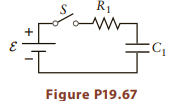
In the circuits in Figures P19.67, P19.70, and P19.72, assume the resistance values are R1 = 1500Ω and R2 = 2400 Ω, and with capacitances C1 = 45 μF and C2 = 25 μF. The emf is ε = 5.5 V. The switches are labeled S.
R1 Figure P19.67
Step by Step Solution
3.50 Rating (160 Votes )
There are 3 Steps involved in it
Assuming the capacitor is initially uncharged current will start high As charge accumulates on the c... View full answer

Get step-by-step solutions from verified subject matter experts