

Question: Figure 11.8 shows that a typical computer system is interconnected with a number of different buses, both internal and external. The diagram includes multiple cache
Figure 11.8
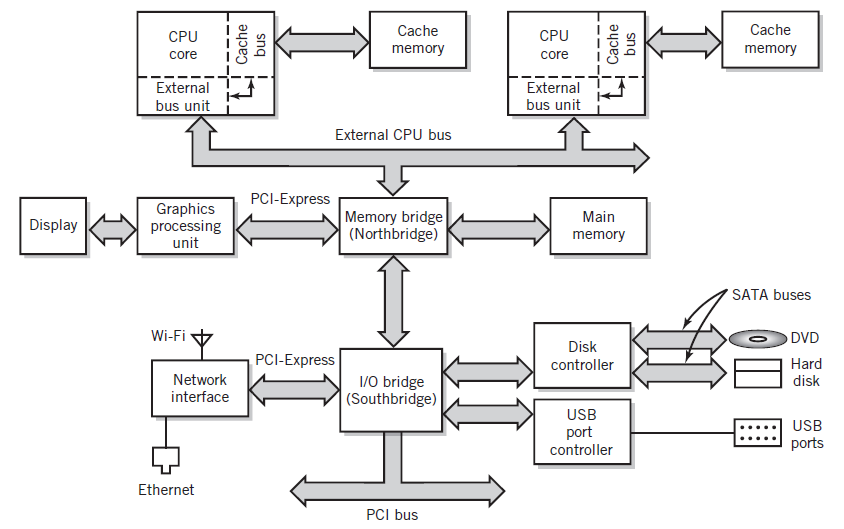
Cache Cache CPU CPU memory memory core core External External bus unit bus unit External CPU bus PCI-Express Graphics processing unit Memory bridge (Northbridge) Main Display memory SATA buses Wi-Fi DVD Disk controller PCI-Express Hard Network disk 1/0 bridge (Southbridge) interface USB port controller USB ports Ethernet PCI bus Cache sng Cache bus
Step by Step Solution
★★★★★
3.40 Rating (153 Votes )
There are 3 Steps involved in it
1 Expert Approved Answer
Step: 1 Unlock

Each bus can be optimized to meet its own requirements For example external buses such as US... View full answer
Question Has Been Solved by an Expert!
Get step-by-step solutions from verified subject matter experts
Step: 2 Unlock
Step: 3 Unlock
Document Format (2 attachments)
1806_60b8c1213b9de_721309.pdf
180 KBs PDF File
1806_60b8c1213b9de_721309.docx
120 KBs Word File