

Figure P12.19 gives the timing diagram of the IEEE 488 bus's data transfer. This bus was first
Question:
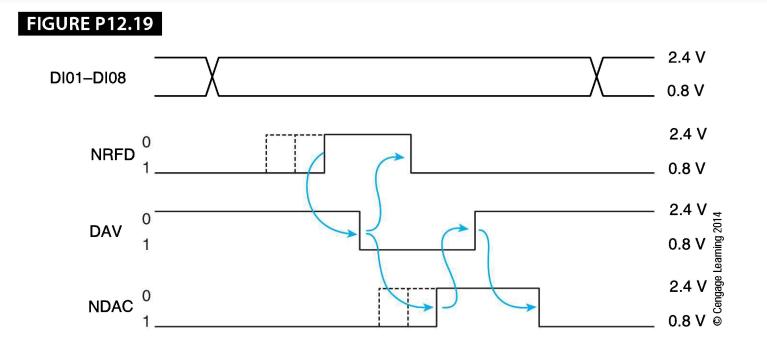
Figure P12.19 gives the timing diagram of the IEEE 488 bus's data transfer. This bus was first designed for use in an intelligent automated instrumentation (laboratory) environment. Multiple asynchronous devices can be connected to the IEEE 488 bus. Not all the devices operate at the same rate. A patented three-wire handshake is used to permit communication between one device and multiple receivers ( or listeners in 488 terminology). The control signals use negative logic ( the O state is the high voltage state) driven by open-collector gates (a device can drive a line to its low voltage state). The three control signals that control the sequencing of data transfer are NRFD (not ready for data, which indicates that a device cannot currently accept data), DAV ( data available , which indicates that a talker has data ready), and NDAC (not data accepted, which indicates that a listener has accepted data). Remember that the use of open-collector bus drivers implements a wired-OR circuit in which the line is pulled to a low level if any driver is pulling it low. Explain in plain language how the three-wire handshake works.
Step by Step Answer:
When one of the listeners becomes free it releases ie negates its NRFD output The negation of NRFD b...View the full answer


Computer Organization And Architecture Themes And Variations
ISBN: 9781111987046
1st Edition
Authors: Alan Clements
