

Question: Test Program 12.5 with the layout specifier in the evaluation shader set to equal_spacing, and then to fractional_even_spacing, as described in Section 12.4. Observe the
Test Program 12.5 with the layout specifier in the evaluation shader set to equal_spacing, and then to fractional_even_spacing, as described in Section 12.4. Observe the effects on the rendered surface as the camera moves. You should be able to observe popping artifacts in the first case, which are mostly alleviated in the second case.
Program 12.5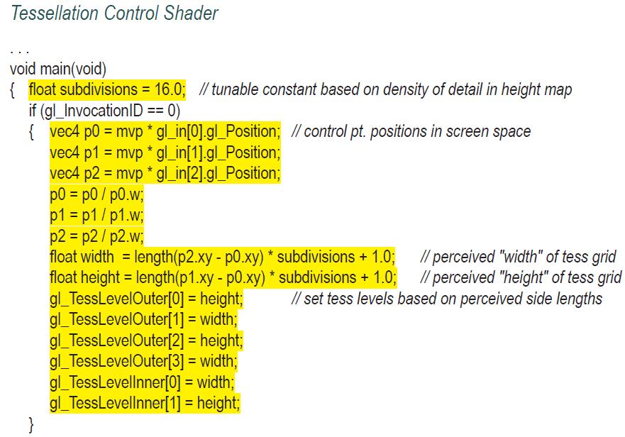
![} //forward texture coordinates and control points to TES as before tcs_out[gl_InvocationID] =](https://dsd5zvtm8ll6.cloudfront.net/images/question_images/1701/6/7/6/914656d8772980aa1701676913896.jpg)
Section 12.4
Using instancing to generate millions of vertices in real time, as in Program 12.4, is likely to place a load on even a well-equipped modern computer. Fortunately, the strategy of dividing the terrain into separate patches, as we have done to increase the number of generated grid vertices, also affords us a nice mechanism for reducing that load.
Of the millions of vertices being generated, many aren’t necessary. Vertices in patches that are close to the camera are important because we expect to discern detail in nearby objects. However, the further the patches are from the camera, the less likely there will even be enough pixels in the rasterization to warrant the number of vertices we are generating!
Changing the number of vertices in a patch based on the distance from the camera is a technique called level of detail, or LOD. Sellers and colleagues describe a way of controlling LOD in instanced tessellation [SW15] by modifying the control shader. Program 12.5 shows a simplified version of this approach. The strategy is to use the patch’s perceived size to determine the values of its tessellation levels. Since the tessellated grid for a patch will eventually be placed within the square defined by the four control points entering the control shader, we can use the locations of the control points relative to the camera to determine how many vertices should be generated for the patch. The steps are as follows:
1. Calculate the screen locations of the four control points by applying the MVP matrix to them.
2. Calculate the lengths of the sides of the square (i.e., the width and height) defined by the control points (in screen space). Note that even though the four control points form a square, these side lengths can differ because the perspective matrix has been applied.
3. Scale the lengths’ values by a tunable constant, depending on the precision needed for the tessellation levels (based on the amount of detail in the height map).
4. Add 1 to the scaled length values, to avoid the possibility of specifying a tessellation level of 0 (which would result in no vertices being generated).
5. Set the tessellation levels to the corresponding calculated width and height values.
Recall that in our instanced example we are not creating just one grid, but 64*64 of them. So the five steps listed above are performed for each patch. Thus, the level of detail varies from patch to patch.
Program 12.4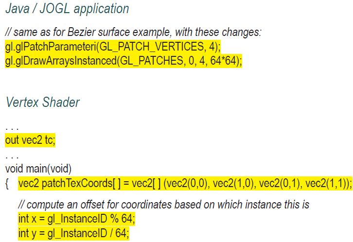
![} // tex coords are distributed across 64 patches, normalized to [0..1]. Flip Y coordinates. tc =](https://dsd5zvtm8ll6.cloudfront.net/images/question_images/1701/6/7/7/028656d87e4a33de1701677026869.jpg)
![} tcs_out[gl_InvocationID] = tc[gl_InvocationID]; gl_out[gl_InvocationlD].gl_Position =](https://dsd5zvtm8ll6.cloudfront.net/images/question_images/1701/6/7/7/041656d87f1f224c1701677040073.jpg)
Tessellation Control Shader void main(void) { float subdivisions = 16.0; // tunable constant based on density of detail in height map if (gl_InvocationID == == 0) {vec4 p0 = mvp * gl_in[0].gl_Position; // control pt. positions in screen space vec4 p1 = mvp * gl_in[1].gl_Position; vec4 p2 = mvp * gl_in[2].gl_Position; p0 = p0/p0.w; P1 = p1/p1.w; p2 = p2/p2.w; float width= length(p2.xy - p0.xy) * subdivisions + 1.0; float height= length(p1.xy - p0.xy) * subdivisions + 1.0; gl_TessLevelOuter[0] = height; = width; gl_TessLevelOuter[1] = height; = width; } gl_TessLevelOuter[2] gl_TessLevelOuter[3] gl_TessLevellnner[0] = width; gl_TessLevellnner[1] = height; // perceived "width" of tess grid // perceived "height" of tess grid // set tess levels based on perceived side lengths
Step by Step Solution
3.43 Rating (153 Votes )
There are 3 Steps involved in it

Get step-by-step solutions from verified subject matter experts