

Question: The asynchronous communication interface shown in Fig. 11-8 is connected between a CPU and a printer. Draw a flowchart that describes the sequence of operations
The asynchronous communication interface shown in Fig. 11-8 is connected between a CPU and a printer. Draw a flowchart that describes the sequence of operations in the transmitter portion of the interface when the CPU sends characters to be printed.
Fig. 11-8
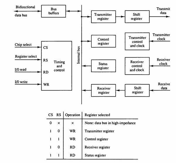
Bidirectional data bus Chip select Register select 1/0 read 1/0 write CS RS RD Bus buffers WR 1 1 1 Timing and control 1 X CS RS Operation Register selected 0 1 0 1 X WR WR RD Internal bus RD Transmitter register Control register Status register Receiver register Shift register Control register Receiver register Status register Transmitter control and clock Receiver control and clock Shift register None: data bus in high-impedance Transmitter register Transmit data Transmitter clock Receiver clock Receive data
Step by Step Solution
3.46 Rating (166 Votes )
There are 3 Steps involved in it
ANSWER step 1 of 2 Refer to Figure 118 given in the textbook The figure shows the asynchronous commu... View full answer

Get step-by-step solutions from verified subject matter experts