

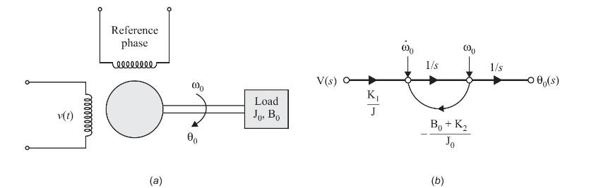
An AC servo motor is shown in Fig. P9.10(a). The voltage (v(t)) applied to control winding, is
Question:
An AC servo motor is shown in Fig. P9.10(a). The voltage \(v(t)\) applied to control winding, is phase displaced by \(90^{\circ}\) with respect to constant amplitude voltage applied to reference phase. The motor is so designed that the developed torque is approximated as
\[\mathrm{T}(t)=\mathrm{K}_{1} v(t)-\mathrm{K}_{2} \omega_{0}(t)\] where \(\mathrm{K}_{1}, \mathrm{~K}_{2}\) are constants and \(\omega_{0}\) is angular velocity of motor shaft. Sketch signal flow graph (state diagram) describing system dynamics and obtain transfer function model \(\theta_{0}(s) / V(s)\).
Step by Step Answer:

This question has not been answered yet.
You can Ask your question!
Related Book For 

Question Posted:
