

Question: For Problem 23 in Chapter 1 we developed the functional block diagrams for the cruise control of serial, parallel, and split-power hybrid electric vehicles (HEV).
For Problem 23 in Chapter 1 we developed the functional block diagrams for the cruise control of serial, parallel, and split-power
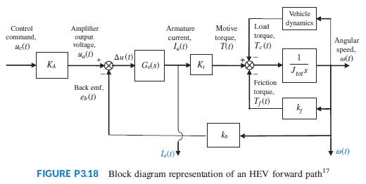
hybrid electric vehicles (HEV). Those diagrams showed that the engine or electric motor or both may propel the vehicle. When electric motors are the sole providers of the motive force, the forward paths of all HEV topologies are similar. In general, such a forward path can be represented (Preitl, 2007) by a block diagram similar to the one of Figure P3.18. Assume the motor to be an armature-controlled dc motor. In this diagram, KA is the power amplifier gain; Ge(s) is the transfer function of the motor electric circuit and consists of a series inductor and resistor, La and Ra, respectively; Kt is the motor torque constant; Jtot, is the sum of the motor inertia, Jm, the inertias of the vehicle, Jveh, and the two driven wheels, Jw, both of which are reflected to the motor shaft; kf is the coefficient of viscous friction; and kb is the back emf constant. The input variables are uc(t), the command voltage from the electronic control unit and Tc(t), the load torque. The output variables in this block diagram are the motor angular speed, ω(t), and its armature current, Ia(t).
a. Write the basic time-domain equations that characterize the relationships between the state, input, and output variables for the block diagram of Figure P3.18, given that the state variables are the motor armature current, Ia(t), and angular speed, ω(t).
b. Write the resulting state-space equations and then represent them in matrix form. Regard the load torque Tc(t) as an extra input to the system. Thus, in your resulting state-space representation, the system will have two inputs and two outputs.
Data From Problem 23:
A linear, time-invariant model of the hypothalamic pituitary-adrenal axis of the endocrine system with five state variables has been proposed as follows (Kyrylov, 2005):
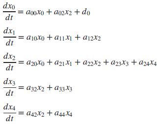
where each of the state variables represents circulatory concentrations as follows:
x0 = corticotropin-releasing hormone
x1 = corticotropin
x2 = free cortisol
x3 = albumin-bound cortisol
x4 = corticosteroid-binding globulin
d0 = an external generating factor
Express the system in the form ẋ = Ax + Bu.
Vehicle dynamics Control Amplifier Armature Motive Load ommand, torque, output voltage, current, torque, T(t) Angular speed, T.(1) Au (1) KA GAs) K, Friction Back emf, torque, eb(t) ko w(1) FIGURE P3.18 Block diagram representation of an HEV forward path"
Step by Step Solution
3.21 Rating (165 Votes )
There are 3 Steps involved in it
ANSWER a The basic timedomain equations for the block diagram in Figure P318 can be writt... View full answer

Get step-by-step solutions from verified subject matter experts