

Question: In Problem 32, Chapter 3, we introduced the idea that when an electric motor is the sole motive force provider for a hybrid electric vehicle
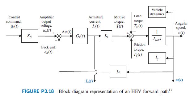
In Problem 32, Chapter 3, we introduced the idea that when an electric motor is the sole motive force provider for a hybrid electric vehicle (HEV), the forward paths of all HEV topologies are similar. It was noted that, in general, the forward path of an HEV cruise control system can be represented by a block diagram similar to that of Figure P3.18 (Preitl, 2007). The diagram is shown in Figure P12.8, with the parameters substituted by their numerical values from Problem 69, Chapter 6; the motor armature represented as a first-order system with a unity steady-state gain and a time constant of 50 ms; and the power amplifier gain set to 50. Whereas the state variables remain as the motor angular speed, ω(t), and armature current, Ia(t), we assume now that we have only one input variable, uc(t), the command voltage from the electronic control unit, and one output variable, car speed, v = rω/itot = 0.06154ω. The change in the load torque, Tc(t), is represented as an internal feedback proportional to ω(t).
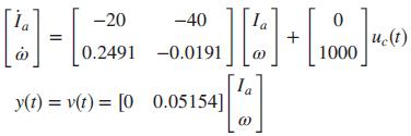
Looking at the diagram, the state equations may be written as
a. Design an integral controller for %OS ≤ 4.32%, a settling time, Ts ≤ 4.4 sec, and a zero steady-state error for a step input To account for the effect of the integral controller on the transient response, use Ts = 4 seconds in your calculation of the value of the naturalfrequency,ωn, of the required dominant poles.
b. Use MATLAB to verify that the design requirements are met.
![0.05154]](https://dsd5zvtm8ll6.cloudfront.net/si.question.images/images/question_images/1612/4/2/3/079601b9fa74876d1612423080230.jpg)
-20 -40 u.(t) 0.2491 -0.0191 1000 la y(t) = v(t) = [0 0.05154]
Step by Step Solution
3.46 Rating (156 Votes )
There are 3 Steps involved in it

Get step-by-step solutions from verified subject matter experts