

Question: Problem 8.54 described an ac/dc conversion and power distribution system for which droop control is implemented through the use of a proportional controller to stabilize
Problem 8.54 described an ac/dc conversion and power distribution system for which droop control is implemented through the use of a proportional controller to stabilize the dc-bus voltage. For simplification, a system with only one source converter and one load converter was considered. The parameters and design considerations presented in that problem, along with some solution results, allow us to represent the block-diagram of that system as shown in the Figure P9.13.
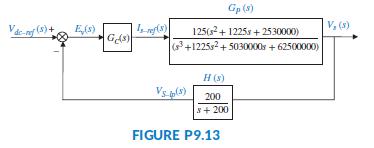
Here Gc(s) is the transfer function of the controller, Gp(s) represents the forward path of the controlled plant (a conversion and power distribution unit), and H(s) is the transfer function of the feedback low pass filter (Karlsson, 2003).
Prepare a table, such as Table 9.5, where the first column, headed Uncompensated, is filled in with your results from the proportional design of Problem 8.54, assuming an input step, vdc-ref (t) = 750 u(t).
Follow Steps 2–8 as described in Section 9.4 (Example 9.5), to design a proportional-plus-integral plus- derivative (PID) controller so that the system can operate with a percent overshoot 4.4 %, a peak time 20% smaller than that of the uncompensated system, and zero steady-state error, eVstep(∞) = 0. Fill in the remaining two columns of your table, PD compensated and PID-compensated.
Data From Problem 8.54:
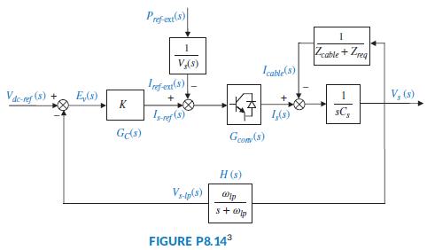
Voltage droop control is a technique in which loads are driven at lower voltages than those provided by the source. In general, the voltage is decreased as current demand increases in the load. The advantage of voltage droop is that it results in lower sensitivity to load current variations. Voltage droop can be applied to the power distribution of several generators and loads linked through a dc bus. In (Karlsson, 2003) generators and loads are driven by 3-phase ac power, so they are interfaced to the bus through ac/dc converters. Since each one of the loads works independently, a feedback system shown in FigureP8.14 is used in each to respond equally to bus voltage variations. Given that
Cs = Cr= 8,000 μF, Lcable = 50 μH, Rcable = 0.06 Ω, Zr= Rr=5 Ω, ωlp=200 rad/s, Gconv(s) = 1, Vdc-ref = 750 V, and Pref-ext = 0, do the following:
a. If Zreq is the parallel combination of Rr and Cr, and Gconv(s) = 1, find
![]()
b. Write a MATLAB M-file to plot and copy the full root locus for that system, then zoom-in the locus by setting the x-axis (realaxis) limits to -150 to 0 and the y-axis (imaginary-axis) limits to -150 to 150. Copy that plot, too, and find and record the following:
(1) The gain, K, at which the system would have complex-conjugate closed-loop dominant poles with a damping ratio ζ = 0.707
(2) The coordinates of the corresponding point selected on the root locus
(3) The values of all closed-loop poles at that gain
(4) The output voltage vs(t) for a step input voltage vdc-ref (t)= 750 u(t) volts
c. Plot that step response and use the MATLAB Characteristics tool (in the graph window) to note on the curve the following parameters:
(1) The actual percent overshoot and the corresponding peak time, Tp
(2) The rise time, Tr, and the settling time, Ts
(3) The final steady-state value in volts
Gp (s) V, (3) 125(s+ 1225s + 2530000) (+1225s2+ 5030000 + 62500000) H (s) Vs pla) 200 s+ 200 FIGURE P9.13
Step by Step Solution
3.32 Rating (161 Votes )
There are 3 Steps involved in it

Get step-by-step solutions from verified subject matter experts